Profile series v.g1 exit device, Step #1 – exit hardware & door prep – SARGENT Profile Series v.G1.5 Exit Devices User Manual
Page 8
6
800-810-WIRE (9473) • www.sargentlock.com • A7757B
Profile Series v.G1 Exit Device
Copyright © 2006, 2008, Sargent Manufacturing Company
, an A
SSA ABL
O
Y
Group company
. All rights reserved.
Reproduction in whole or in part without the express written permission of Sargent Manufacturing Company is prohibited.
Installation Instructions for Rim Type
Exit Device 8877/8878
Inside
Outside
Left Hand
Reverse Bevel
"LHRB"
Right Hand
Reverse Bevel
"RHRB"
IMPORTANT: BEFORE STARTING
• This device is non handed
• Door should be fitted and hung
• Verify box label for size of exit device, function and hand
Step #1 – Exit Hardware & Door Prep
1. If using a mullion, install in frame.
2. Prep door according to Exit installation instructions A6770 and appropriate template
(metal door 4535 and 4536; wood door A7458 and A7459).
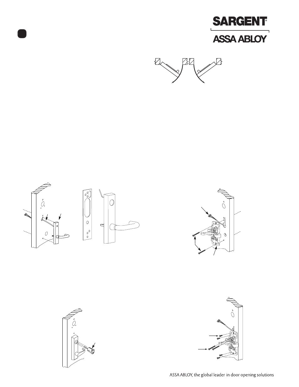
Step #2 – Installation of Outside Trim, Exit Chassis and Cylinder
A. Outside Trim
1. For exterior applications “ET” gasket (52-0263)
should be used to seal between “ET” escutcheon
and outside door surface
2. Route harness through under cut of cylinder hole
and out to other side of door
3. Place “ET” control onto door
B. Inside Trim
1. Route “ET” harness along track cutout for wood
doors and access hole for metal doors
2. Mount exit chassis carefully. DO NOT PINCH
HARNESS WIRES
3. “ET” spindle will engage into the hub of exit device
chassis
4. Secure chassis and “ET” with (2) 1/4 -20 x 2-3/8"
flat head machine screws
C. Cylinder Installation
NOTE: For devices without cylinder, go to Step D2.
1. Insert cylinder into “ET” control
2. Mate cylinder tailpiece into hub of exit device
chassis
3. Make sure “ET” harness is clear of cylinder and
cylinder tailpiece
D. Securing Cylinder
1. Secure cylinder to exit chassis using (2) #12-24 x
1-7/8" connecting screws
2. Fasten exit chassis to door using (4) #10 wood
screws or #10-24 machine screws
#34
Cylinder
ET Control
Wire
harness
Wire harness
(2) 1/4-20 x 2-3/8"
Flat head
machine screws
secures ET
Exit Chassis
(2) #12-24 x 1-7/8"
Flat head connecting
screws for cylinders
(4) #10 Wood
screws or #10-24
machine screws
Outside
of door
ET gasket
Inside
of door
Outside
of door
Inside
of door
6