Profile series v.g1 exit device, Step #3 – attach fire stop plate, Mortise installation instructions (continued) – SARGENT Profile Series v.G1.5 Exit Devices User Manual
Page 14: Step #4 – installation of outside escutcheon
12
800-810-WIRE (9473) • www.sargentlock.com • A7757B
Profile Series v.G1 Exit Device
Copyright © 2006, 2008, Sargent Manufacturing Company
, an A
SSA ABL
O
Y
Group company
. All rights reserved.
Reproduction in whole or in part without the express written permission of Sargent Manufacturing Company is prohibited.
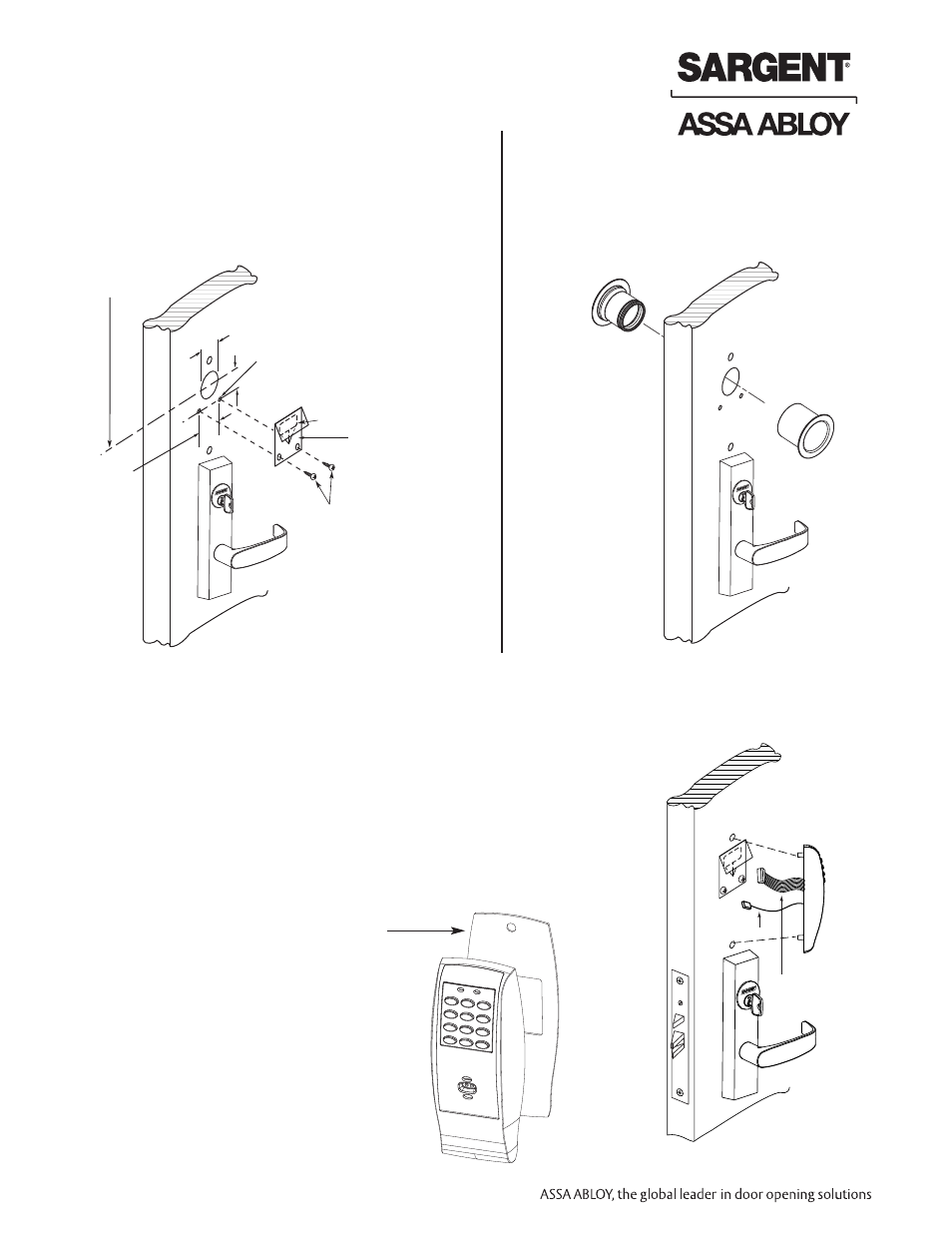
Step #3 – Attach Fire Stop Plate
C
L OF 1-1/2" Dia.
(2) Self tapping
screws #8 x 1/2"
long for wood &
metal doors
(2) 1/8" Dia.
holes required
Slot
1-1/2" Dia.
7/8"
1-1/2"
Fire stop
plate
NOTE: Fire stop plate
is required on all fire
rated doors only
NOTE: Required for 12- Fire Rated doors only
1. Drill (2) 1/8" diameter holes if the door is not supplied
with them
2. Secure fire stop plate to door with (2) #8 x 1/2" self
tapping screws
Mortise Installation Instructions (Continued)
A. Insert Wires and Connector
1. For exterior applications gasket (68-1400) should be used
to seal between escutcheon and outside door surface
2. For 12- fire rated devices feed keypad ribbon cable/connector
from outside of door through gasket then fire stop plate
3. For non-12- exit devices, feed connector and wires through
gasket then hole in door
4. Place escutcheon against door surface
Wires & Connector
go through fire
stop plate
Ground wire
Keypad ribbon
cable/connector
Step #4 – Installation of Outside Escutcheon
For exterior applications
gasket (68-1400) should be
placed between the
escutcheon and the
door surface
-
+
-
+
-
+
-
+
+
-
+
-
Non Fire Rated Exterior Doors-
Install Weather Conduit
(P/N 52-2847) as shown below