Installation – Tweco 2460 Heavy Duty CC CV Control Wire Feeder User Manual
Page 43
BASE ASSEMBLY NO. 375769-1 & -4
DESCRIPTION AND INSTALLATION INSTRUCTIONS
Description
The base is designed for use in assembling a
composite Series 2000 Wire Feeder. It is a compo-
nent which makes it possible to bring together a
Control Box and Feedhead Assembly (which have
their own TIP Instruction Sheets), and a Wire Spool
Support Assembly.
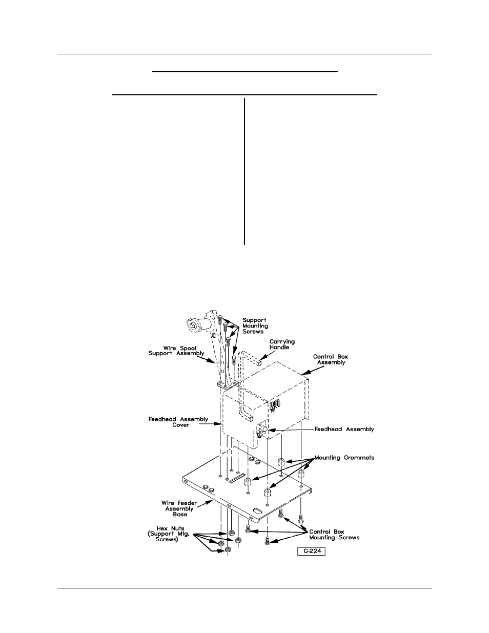
Installation
The illustration below shows the mounting of the
Control Box, Feedhead Assembly, and the Wire
Spool Support Assembly.
1. To mount the Control Box Assembly, align holes
in the base with the grommets (in the Control Box
bottom panel), insert the self-tapping mounting
screws through the holes in the base, into the nylon
grommets.
2. Tighten the screws in place, which will expand
the nylon grommets in the holes in the Control Box
bottom.
NOTE: The Feedhead Assembly is se-
cured to the Control Box, and does not
bolt directly to the base.
3. Align four holes in the bottom flange on the Wire
Spool Support with four holes in the base (as shown
in illustration) and insert four capscrews through the
holes in the base and stiffener (underneath the
base) and secure in place with the four hex nuts.
TIP-127
BASE ASSEMBLY NO. 375769-1 & -4
May 17, 1996 Revised
Page 1