Tweco 2460 Heavy Duty CC CV Control Wire Feeder User Manual
Page 32
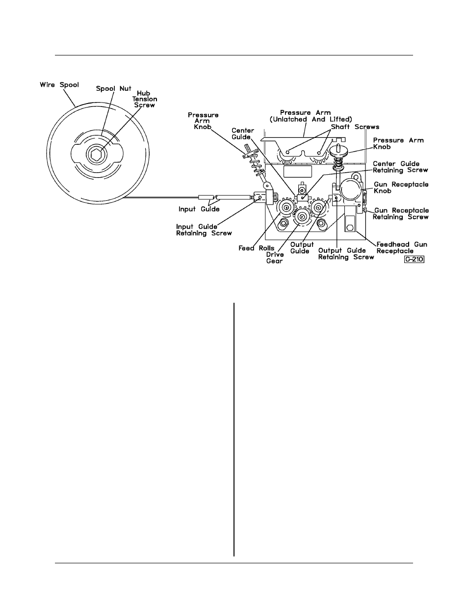
Installing Gun and Cable Assembly — Refer to
Figure 3. The Feedhead is designed for use with
TWECO Guns and Cables. To install one of these
guns, loosen the Gun Receptacle Knob and insert
the gun Quick Connect Receptacle into the Feed-
head until it bottoms out against the Output Guide.
Tighten Gun Receptacle Knob. See “A” and “B”
assemblies on Figure 3.
If a TWECO #5 Backend Gun and Cable is to be
installed, the Gun Sleeve must be removed, the Gas
Inlet must be removed and replaced with another
one. See “B” on Figure 3. The Gas Inlet comes in a
kit (375999). To install the Gun and Cable, proceed
as follows:
1. Remove the Gun Receptacle Knob.
2. Remove the two retaining screws which secure
the Gas Inlet into the Feedhead Plate. This allows
the Gas Inlet to pull straight out.
3. Hold the Gas Tube (with hose attached) and
turn the Gas Inlet counterclockwise to unscrew and
remove it. Screw the Gas Tube into the Gas Inlet
provided in kit 375999, but do not yet install the Gas
Inlet into the Feedhead.
4. Hold the Gun Receptacle and remove the Gun
Sleeve (used only on the TWECO #4 Backend
Guns). Lower the Gun Receptacle.
NOTE: If the Gun Sleeve does not come
out easily, insert a screwdriver into the
slot (see Figure 3) and gently, but firmly,
pry the sleeve out.
5. Slide the new Gas Inlet (with Gas Tube in-
stalled) into place, making sure that the wide
groove, toward feed rolls, goes in first.
6. Replace the Retaining Screws to secure the
Gas Inlet into place.
NOTE: When the TWECO #5 Backend
Gun and Cable is installed, it may be nec-
essary to change the Output Guide, de-
pending upon new wire size. See
instructions for changing Output Guide in
Installing Feed Rolls and Guides.
7. Raise the Gun Receptacle and reinstall the Gun
Receptacle Knob. Do not tighten at this time.
8. Insert the quick-connect receptacle on the Gun
Cable into the Feedhead, and tighten the Gun Re-
ceptacle Knob to a “snug” position. See Gun and
Cable Manual for details on these parts.
9. Attach electrode lead to the Gun Receptacle by
use of a bolt in the threaded hole at the lower end
of the receptacle.
Figure 2
TIP-219
FEEDHEAD ASSEMBLY NO. 376799A-1, -2, -3, -4
Page 2
December 1, 1997 Revised