Controls and connections – Tweco 2460 Heavy Duty CC CV Control Wire Feeder User Manual
Page 25
CONTROL BOX ASSEMBLY NO. 376783A & 376783B
DESCRIPTION, INSTALLATION, OPERATION AND MAINTENANCE
Description
The Control Box assembly is the control medium
for the operation of the Feedhead. Wire Feed Speed
rate (IPM Inches-per-minute) is selected and regu-
lated by the knob (potentiometer) on the front panel.
The box is designed to function as a component of
the 2000 Series Wire Feeder composite assembly,
or as remote-mounted control medium, not situated
close to the Feedhead. A side panel is available to
replace the Feedhead Mounting Plate (see Figure
1) when used in a remote situation.
Controls and Connections
A. CV operation. When using a CV power source,
this control is used to control wire feed speed. To
increase wire feed speed, turn the control knob
clockwise. To decrease wire feed speed, turn the
knob counterclockwise.
B. CC operation. When using a CC power source,
this control is used to control arc voltage by varying
wire feed speed. To increase arc voltage (decrease
wfs), turn knob counterclockwise. To decrease arc
voltage (increase wfs), turn knob clockwise.
NOTE: Many CC power sources have a
drooping V-I characteristic. On these
types of power sources, the current is not
exactly constant and changing the arc
voltage will also change the output cur-
rent. This again becomes a self-regulat-
ing stable system.
ON-OFF Rocker Switch — This switch controls the
input circuit, applying or removing the input voltage
of the unit.
Gun Switch Receptacle — The gun switch control
cable connects to the gun switch receptacle (quick-
disconnect type) to provide control from the gun
switch to the wire feed mechanism.
Welding Gun Cable Connector — The gun cable
is connected to the wire feeder at this receptacle.
Connections must always be tight.
Fuse 7 A — The unit is equipped with a 7 A MDX
slow blow fuse. This fuse is rated at 125 volt and
may
never
be replaced with a fuse of lower voltage
rating as this could cause serious damage to the
equipment.
Fuse 1/8 A — Protects P.C. Board from welding
electrode shorting to gun switch circuit.
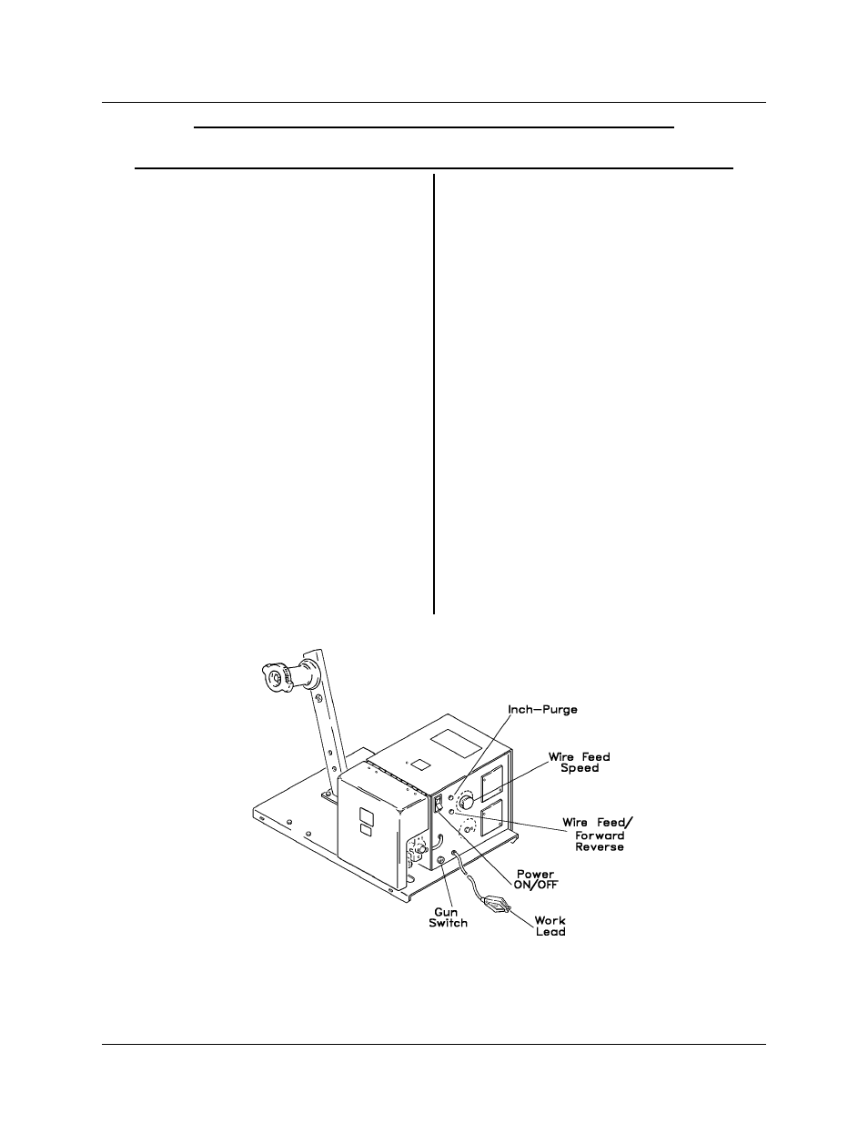
Figure 1 Controls - Connections (Front End)
TIP-218
CONTROL BOX ASSEMBLY NO. 376783A & 376783B
May 29, 1996 Revised
Page 1