Tabulated data, Control box assembly, Wire reel support assembly – Tweco 2460 Heavy Duty CC CV Control Wire Feeder User Manual
Page 14: Baseplate, Options
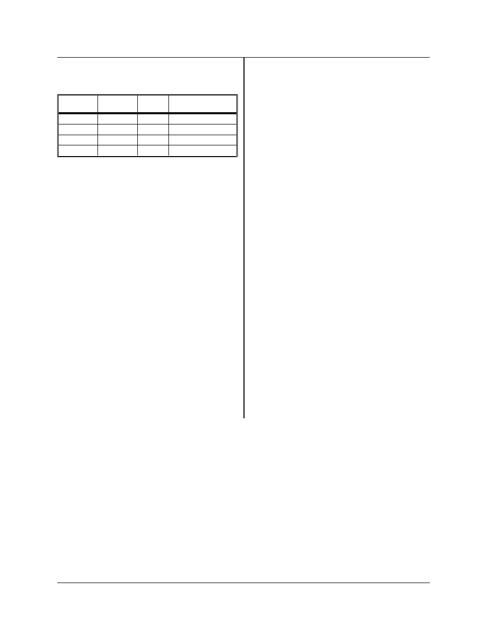
depending upon which wire feed rate is desired. See
Table 3-1 for correlation of numbers.
The assemblies consist of Feed Rolls (which are
made up of a Gear and Feed Roll) for various wire
types and/or sizes, Wire Input Guide, Output Guide,
Feedhead Mounting Plate, and Pressure Arm as-
sembly. The drive motor is 24 volts DC. See TIP-218
for details on the Feedhead Assembly. See Feed
Roll Kit drawing 375980 for selecting part numbers
for the Feed Rolls, Wire Guides, Contact Tubes, etc.
Tabulated Data
Gearmotor
Permanent magnet
24 V DC, 1/8.8 HP
5A
±
.5 amps
Speed:
123 RPM
±
12 RPM
57 RPM
±
5.7 RPM
(optional @ no
load)
Voltages
Motor
24 V DC
Gun Circuit
11 V DC or 24 V AC
(option)
Speed Range of Wire
20.4:1 drive gear ratio — 40 to 600 IPM
(inches/minute)
43.9:1 drive gear ratio — 20 to 300 IPM
(inches/minute) (optional)
Wire Data
Spool weight
60 pounds
(27.2 kg) max.
Sizes
1/8 inch (3.17 mm)
and smaller
Control Box Assembly
The Control Box contains control and connection
for the operation and component hook-up with the
particular welding system it is being used with. See
TIP-218 and MPL-224 included in this manual.
Wire Reel Support Assembly
The support bolts in place at the rear of the base-
plate. See I-169 included in this manual for details
on the installation and operation of the wire support
assembly.
Baseplate
See TIP-127 for details on the baseplate used for
this wire feeder when assembled to make the sub-
ject model configuration.
Options
The options available with this unit are as follows:
SPEC.
MODEL
FEED
ROLLS
WIRE FEED
RATE
6877A-1
2460
4
40-600 IPM
6877B-1
2460
4
40-600 IPM
6877A-2
2460
4
20-300 IPM
6877B-2
2460
4
20-300 IPM
Table 3-1
430429-249
DESCRIPTION OF EQUIPMENT
3-2
May 22, 1997 Revised