Installation – Tweco 2460 Heavy Duty CC CV Control Wire Feeder User Manual
Page 31
FEEDHEAD ASSEMBLY NO. 376799A-1, -2, -3, -4
DESCRIPTION, INSTALLATION, OPERATION AND MAINTENANCE
Description
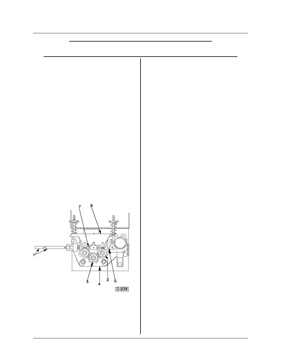
The four-roll feedhead assembly consists of four
idler gear/feed rolls (item 2, Figure 1) for various
types and sizes of wire. See Feed Roll Kit (375980),
wire input guide (item 1), center guide (item 7),
output guide (item 5), feedhead plate (item 4) and
pressure arm assembly (item 6). The drive motor is
115 volt DC, controlled by solid-state or variac
speed control. See the data on the particular model
which is found in the manual of which this TIP is a
part.
Wire sizes from 0.030-inch (0.76 mm) diameter to
1/8 inch (3.18 mm) may be fed with selection of
proper feed rolls. See Feed Roll Kit (Drawing
375980-X, included in this manual) for feed roll
configuration and proper feed rolls for given sizes
and types of wire.
The Solenoid (Gas Control) Valve (optional) is
located on the back side of the Feedhead Plate. A
fitting for gas supply extends through the back panel
of the Control Box.
Installation
The feedhead assembly becomes a part of the
modular assembly which includes a control box
assembly, and a wire support assembly which may
be mounted on a common baseplate, or remotely
mounted, as on a boom unit.
Location — For best operating characteristics and
longest unit life, take care in selecting an installation
site. Avoid locations exposed to dust, high ambient
temperature, or corrosive fumes.
Connections — The electrical connections for the
wire feeder are made both at the feedhead and
control box. The feedhead connection is made from
the power supply terminal to the feedhead as with
standard feeders. However, the feeder motor and
controls use the feedhead potential to supply oper-
ating power for the feeder. Be sure the cable con-
nection to the feedhead is tight. A loose cable will
cause the feeder to malfunction.
Installation of Welding Wire Spool — See I-169 for
details.
Adjustment of Spool Tension — Adjust the tension
on the Wire Spool so that the wire will feed freely
into the feedhead (feed rolls), but will not “coast”
when wire feeding stops. Tighten or loosen the Hub
Tension Screw accordingly.
Threading Wire Into Feedhead — Refer to Figure
2.
CAUTION: Use care when handling the
spooled wire as it tends to unravel when
loosened from the spool. Grasp the end
of the wire firmly; do not let it get away!
Make sure the end of the wire is free of
burrs, and that it is straight.
1. Loosen the Pressure Arm Knobs, and raise the
Pressure Arm UP as shown in Figure 2.
2. Place the end of the wire into the Input Guide,
feeding it through the guide and over the feed roll
grooves.
3. Pass the wire into the Output Guide and on into
the Gun Cable. See Owner’s Manual for the Gun
and Cable Assembly.
4. Make sure that the wire is directly over the
grooves in the feed rolls and replace the Pressure
Arm. Lock it in place with the Pressure Arm Knobs.
Figure 1
1. Input Guide
2. Idler Gear/Feed Roll
3. Drive Gear
4. Feedhead Plate
5. Output Guide
6. Pressure Arm
Assembly
7. Center Guide
TIP-219
FEEDHEAD ASSEMBLY NO. 376799A-1, -2, -3, -4
December 1, 1997 Revised
Page 1