Operation, Maintenance – Tweco 2460 Heavy Duty CC CV Control Wire Feeder User Manual
Page 34
NOTE: An Allen wrench is supplied for
tightening the Feed Roll Screws. It is
“stored” in a nylon retainer, located on
the rear end of the Feedhead Cover. See
Figure 6.
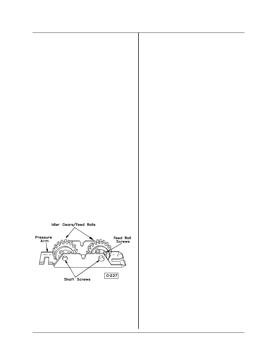
6. To install the upper two Feed Rolls, follow the
procedure below:
a. Remove shaft screws which secure the
Idler Gear/Shaft in place in the pressure arm.
See Figure 5.
b. Install the Feed Rolls onto the Idler Gears,
and secure in place with the Feed Roll
Screws. See Figure 4.
NOTE: When installing a Style 4 Feed
Roll, which is made up of two pieces, be
sure to place the narrow piece on the
gear first. This makes the groove line up
with the Guides.
c. Reinstall the Idler Gears/Feed Rolls into
the Pressure Arm. Fasten in place with the
Shaft Screws. See Figure 5.
d. Reassemble Pressure Arm onto the Feed-
head Assembly by dropping it into place (see
Figure 2) and adjusting the Pressure Arm
Knobs for proper tension. Adjust Center
Guide so that clearance between Guide and
the first Feed Roll is approximately 1/32 inch
(0.8 mm). Tighten Center Guide Retaining
Screw.
Input Guides
1. Loosen the Input Guide Retaining Screw and
pull the Input Guide Spring (Item 1, Figure 1) out of
the hex nylon Input Guide.
2. Insert the steel or nylatron Input Guide into the
hex nylon Input Guide.
NOTE: The hex nylon Input Guide is a
holding device for the Input Guide Spring
and the Input Guide which is supplied in
the Feed Roll and Guides Kit (375980-*).
*The dash number denotes which Feed
Rolls and Guides are furnished.
3. Reinstall the Input Guide Spring, pushing it
against the Input Guide, and tighten the Retaining
Screw.
Output Guide — The Output Guide may be in-
stalled with the Gun Sleeve and the Gas Inlet (all
models) in place.
1. Loosen the Output Guide Retaining Screw (see
Figure 2), and turn it out far enough to allow the
Guide to slide in or out.
2. Insert the Guide into the Feedhead with long-
nosed pliers or a piece of welding wire. Push the
Guide up to the Feed Rolls until it “bottoms out”
inside the Feedhead and tighten the Retaining
Screw.
3. Proceed to install the Gun and Cable Assembly
as detailed above under Installing Gun and Cable
Assembly.
Operation
The operation of this feedhead is a function of the
wire feeder assembly of which it becomes a part.
See the Wire Feeder Manual for the 2000 Series for
details which affect this operation.
Maintenance
Cleaning — Periodically blow off the feedhead
assembly with clean, dry, compressed air of not
more than 25 psi (172 kPa) pressure. Use care to
not strike component parts of the feedhead with the
air hose nozzle.
Cleaning Feed Rolls and Gears — Using a small
wire brush, clean the grooves on the feed rolls and
gear teeth frequently. To clean the wire groove,
loosen the Pressure Arm Knob and raise the Pres-
sure Arm. Remove the wire from the feed rolls.
Clean the gear teeth and check the screws which
hold the feed rolls on the gears.
Feedhead Maintenance — The only point of main-
tenance in the feedhead assembly is the motor
brushes. To inspect and/or change the brushes, the
feedhead assembly must be removed from the Con-
Figure 5
TIP-219
FEEDHEAD ASSEMBLY NO. 376799A-1, -2, -3, -4
Page 4
December 1, 1997 Revised