05 primary power connections, Primary power connections -5, Auto-cut 200 xt – Tweco 200 XT Auto-Cut 380V User Manual
Page 29
AUTO-CUT 200 XT
Manual 0-5253
INSTALLATION
3-5
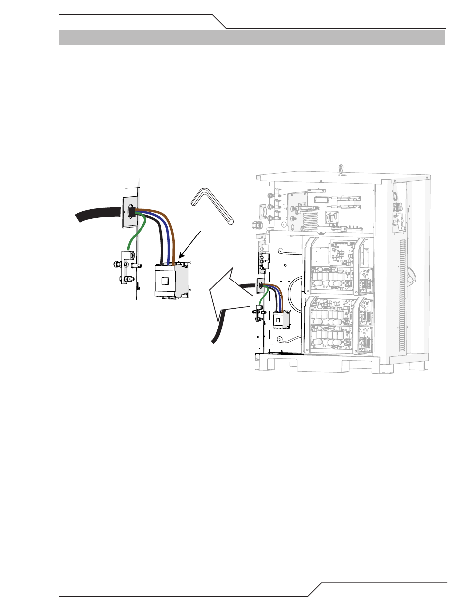
3.05 Primary Power Connections
The primary power cable and through hole cable grip must be supplied by the end user and connected to the power
supply. Refer to local and national electrical codes for suggested cable and fuse sizes.
Remove the left side covers of the Power Supply.
Connect Input Power and System Ground Cables
1. Carefully cut back the outer sheath on the primary input power cable to expose the individual wires. Cut back
the insulation on the individual wires. Route the cable through the rear panel of the power supply.
2. Insert the individual wires into the proper terminals on the contactor as shown. There are factory installed wires
already attached to these same terminals and will need to be loosened first. Do Not remove these wires. Tighten
the screws onto both sets of wires using a 4mm hex key wrench.
Art # A-11550
4mm
3. Connect the input power cable ground wire to the ground terminal block as shown above.
4. Connect a system ground cable (F1) to the ground terminal on the outside of the power supply located next to
the Torch Leads port. Refer to the Ground Connections Section for full details and procedures on proper system
grounding.