05 cut quality, 05 cut quality -5 – Tweco CE PAK Master 150XL Without Latch Circuit User Manual
Page 37
Manual 0-2696
4-5
OPERATION
B. Deionizer Bag Inspection
Check the condition of the deionizer bag in the reservoir
basket. If the bag is a yellowish brown (straw color) then
replace the bag.
C. Torch Parts Selection
Check the torch for proper parts assembly. Install proper
torch parts for the application (refer to Torch Instruction
Manual).
D. Primary Input Power Source
Check the power source for proper input voltage. Make
sure the input power source meets the power requirements
for the unit per Section 2.03, Specifications/Design Fea-
tures.
Connect the input power cable (or close the main discon-
nect switch) to supply power to the system.
E. Plasma Gas Supply Selection
Select desired plasma gas. Make sure gas sources meet
requirements (refer to Torch Instruction Manual).
Check connections and turn plasma gas supply on.
F. Secondary Gas Supply Selection
Select desired secondary gas. Make sure gas sources
meet requirements (refer to Torch Instruction
Manual). Check connections and turn secondary
supply on.
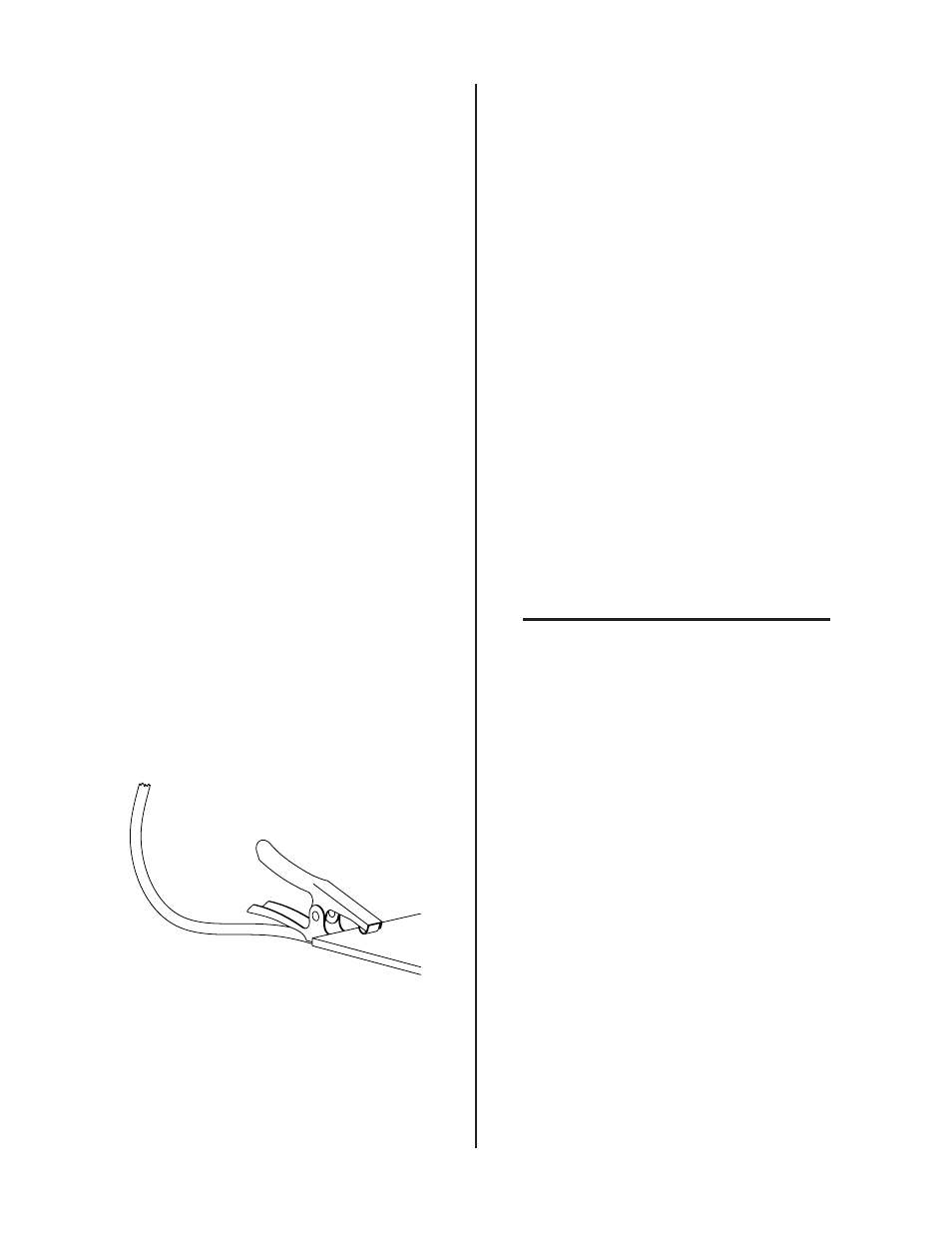
G. Work Cable Connection
Check for a solid and clean work cable connection to
the workpiece. The area must be free from paint and
rust.
A-02081
Figure 4-6 Work Cable Connection to Workpiece
H. Torch Connection
Check that torch is properly connected.
I.
Plasma Gas Purge (Pre-Flow)
Move the ON/OFF switch to ON position. To start the pre-
flow move the RUN/SET switch to SET position for a mini-
mum of 20 seconds. The gas purge will remove any mois-
ture that may have accumulated in the torch and leads
while the system was shut down. The torch cannot be
activated during gas purge process.
J. Current Output Level Selection
Select the desired current output level for the operation.
• 30-120 amps for standoff cutting and gouging
• 30 - 35 amps for drag cutting
K. Set Operating Pressure
Move the RUN/SET switch to SET position. Set plasma
and secondary pressures. Adjust the gas pressure to 65
psi (4.5 bar) for plasma and 60 psi (4.1 bar) for secondary.
L. Ready for Operation
Return the RUN/SET switch to RUN position. The system
is now ready for operation.
NOTE
Refer to Appendix 2 for a detailed block diagram
of the Sequence of Operation.
4.05 Cut Quality
Cut quality requirements differ depending on application. For
instance, nitride build-up and bevel angle may be major factors
when the surface will be welded after cutting. Dross-free cut-
ting is important when finish cut quality is desired to avoid a
secondary cleaning operation.
The following cut quality characteristics are illustrated in Fig-
ure 4-7:
Cut Surface
The condition (smooth or rough) of the face of the cut.
Bevel Angle
The angle between the surface of the cut edge and a plane
perpendicular to the surface of the plate. A perfectly per-
pendicular cut would result in a 0° bevel angle.
Top-Edge Rounding