Tweco CE PAK Master 150XL Without Latch Circuit User Manual
Page 24
INSTALLATION
3-6
Manual 0-2696
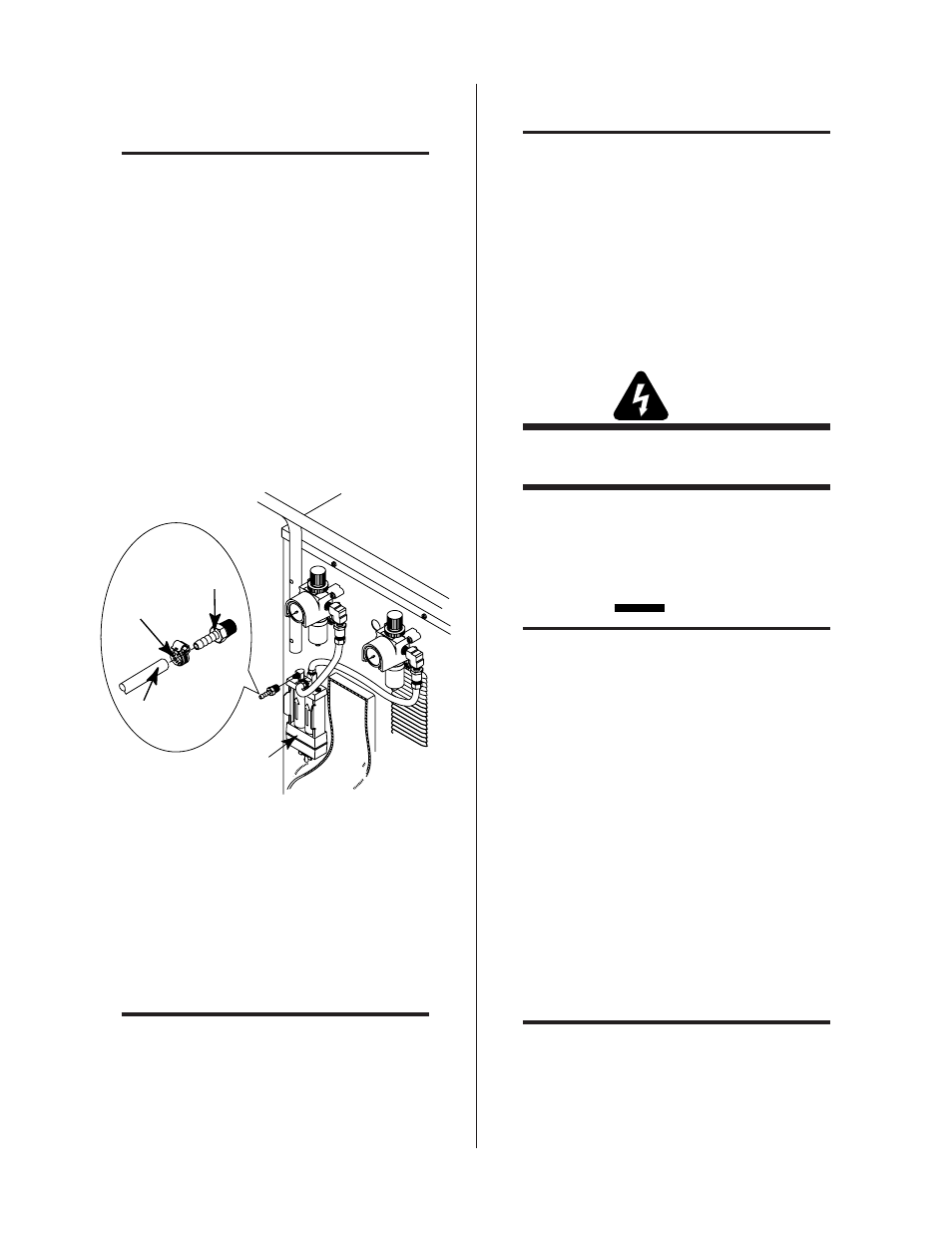
B. Using Shop Air Only with Optional Two
Stage Filter Assembly
NOTE
For units where the Optional Two Stage Air Line
Filter has not been factory installed, install the Fil-
ter Assembly according to the instructions provided
with the assembly.
The following procedure is the recommended shop air connec-
tion method when using the optional two stage air filter:
1. Remove the factory installed plug fitting from the end of the
Fitting in the input port (IN) of the Two Stage Air Line Filter
Assembly.
2. Locate the 1/4 NPT to #4 (6 mm) barbed hose fitting shipped
inside the Torch Spare Parts Kit.
3. Install the barbed fitting into the input port (IN) of the Two
Stage Air Filter.
A-02085
Two Stage
Filter
Assembly
Barbed
Hose
Fitting
Gas Supply Hose
Hose
Clamp
Figure 3-7 Shop Air Connections - Optional Two Stage
Air Line Filter Assembly
4. Tighten the barbed fitting.
5. Connect the air supply hose (see NOTE) to the barbed fit-
ting and secure with a customer supplied hose clamp.
NOTE
The customer supplied hose must be at least a #4
hose (1/4 inch or 6 mm I.D.) to provide adequate
air flow.
C. Using High Pressure Gas Cylinders Only
NOTES
Refer to the manufacturer’s specifications for in-
stallation and maintenance procedures. Refer to
sales literature for a listing of available high-pres-
sure regulators and accessories.
Do not use an air line filter with high pressure regu-
lators.
1. Examine the cylinder valves to be sure they are clean
and free of oil, grease or any foreign material. Mo-
mentarily open each cylinder valve to blow out any
dust which may be present.
WARNING
Do not stand in front of valve outlet when open-
ing.
2. Each cylinder must be equipped with an adjustable
high-pressure regulator capable of outlet pressures up
to 100 psi (6.9 bar) maximum and flows of up to 400
scfh (188.7 lpm).
CAUTION
Pressure should be set at 100 psi (6.9 bar) at the
high pressure gas cylinder regulator.
3. When using gas cylinders as the plasma and second-
ary gas supplies the connections will depend on the
number of cylinders used. Refer to one of the follow-
ing procedures and make the gas connections.
• Using Single Gas Cylinder for Plasma and Sec-
ondary Gas
If the Plasma and Secondary gas source are to be
the same and will use the same high pressure cyl-
inder, connect the gas regulator supply hose from
the gas cylinder to the Power Supply as follows:
a. Remove the factory installed plug fitting from the
end of the T-Fitting on the "Y" Hose Assembly.
b. Install a 1/4 NPT-Insert B (right-hand) Adapter Fit-
ting (see NOTE) into the end of the T-Fitting.
NOTE
Adapter Fitting must be supplied by the customer.
c. Connect the customer supplied gas regulator sup-
ply hose directly to the Adapter Fitting.