Tweco PakMaster 100XL Plus User Manual
Page 24
SECTION 4: OPERATION
18
Manual 0-2784
3. RUN/SET/LATCH Switch
RUN position is used for general torch operation
(torch switch must be held). SET position used for
setting pressure and purging gas lines. LATCH posi-
tion is used for specific applications (torch switch can
be released after main arc transfer).
4. AC Power Indicator
Green LED indicator will blink ON then OFF for ap-
proximately eight seconds and then stay ON after the
ON/OFF power switch is set to ON. Indicates oper-
ating power is present in the unit..
5. TEMP Indicator
Normally OFF. Yellow LED indicator will come ON
when the internal temperature sensors detect tempera-
tures above normal limits. The unit should be allowed
to cool before continuing operation.
6. GAS Indicator
Green LED indicator will come ON when the input
gas pressure is set to 45 psi (3.1 bar) or higher. Indica-
tor will be OFF when the pressure falls below 45 psi
(3.1 bar).
7. DC Indicator
Green LED indicator will come ON while the torch
switch is pressed.
C. Torch Panel Bulkhead
The torch panel bulkhead is located under the access
panel.
1. Pilot Lead Stud
Connects the pilot control wire on the torch to the unit.
2
1
3
A-00923
Figure 4-3 Torch Panel Connections
2. Control Cable Connector
Connects the torch switch to the unit. In machine torch
applications connects the torch switch on the pendant
to the unit.
3. Gas/Power Lead Connection
Connects the torch gas/negative lead to the unit.
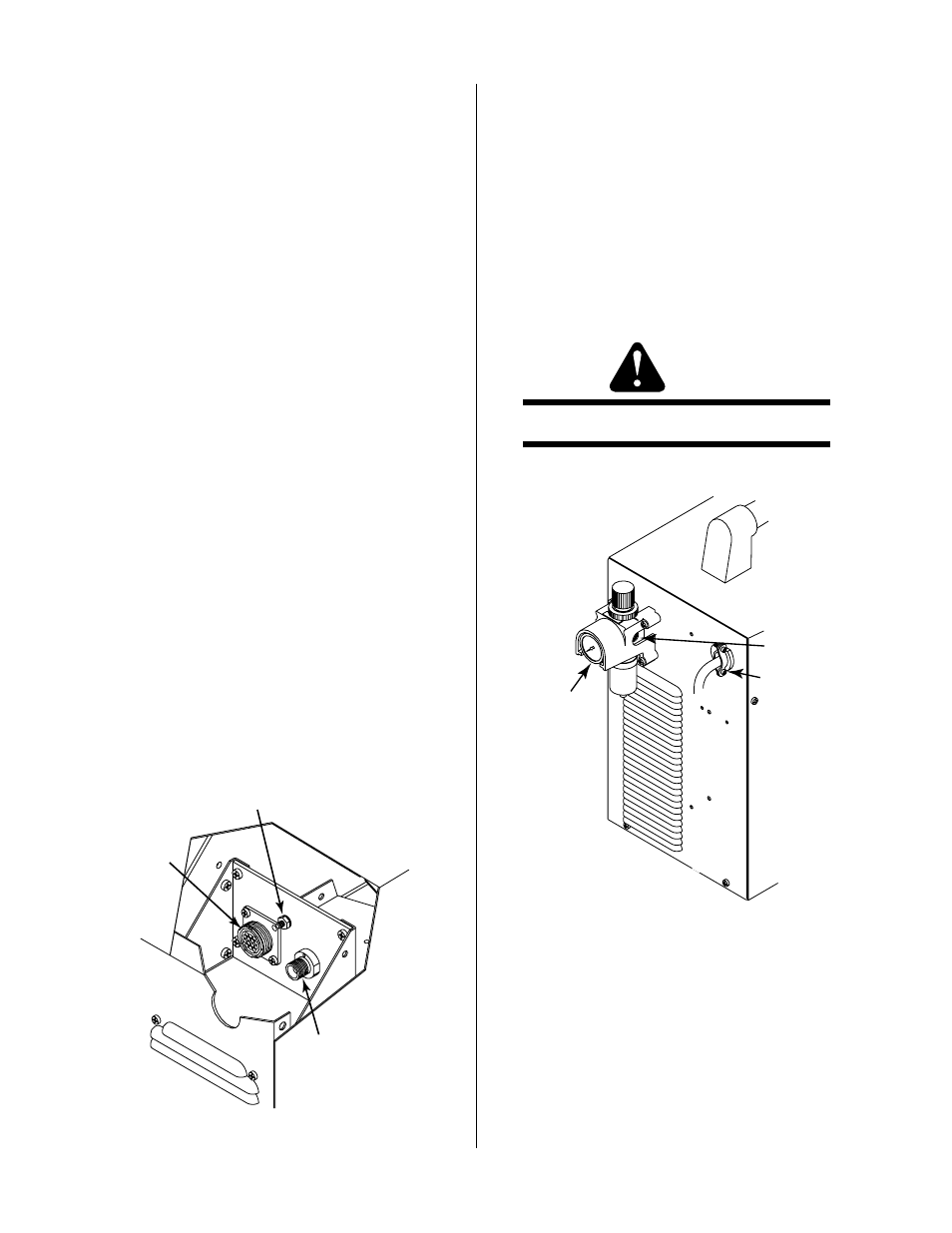
D. Rear Panel
1. Gas Input
Input connection for air or nitrogen (N2) input.
WARNING
This unit not to be used with oxygen (O
2
).
1
2
3
A-02605
Figure 4-4 Rear Panel
2. Primary Input Power Cable
Four-conductor Input Power Cable with filtering
beads. Three-Phase primary input power cable ca-
pable of handling the input voltage designed for this
unit. Plug is not supplied with unit.