Section 4: operation, 01 introduction, 02 functional overview – Tweco PakMaster 100XL Plus User Manual
Page 23: 03 operating controls, Section 4, Operation
Manual 0-2784
17
SECTION 4: OPERATION
SECTION 4:
OPERATION
4.01 Introduction
This section provides a description of the Power Supply
operating controls and procedures. Identification of the
Front and Rear Panel components is followed by operat-
ing procedures.
4.02 Functional Overview
The Power Supply provides a degree of operating flex-
ibility and the use of simple controls.
4.03 Operating Controls
This subsection provides specific functional descriptions
of the Power Supply operating controls and indicators.
A. Front and Side Panel
1. Control Panel
All operator controls, except gas pressure adjustment,
are located on this panel. Power ON/OFF and RUN/
SET/LATCH switches; CURRENT control; LED indi-
cators for AC Power, TEMP, GAS, and DC.
A-02458
1
2
3
4
5
Figure 4-1 Front and Side Panel Connections
2. Access Panel
A panel to gain access to the bulkhead area contain-
ing the torch connections.
3. Torch Leads Input
Hole in the front panel to feed the torch leads through
to the internal bulkhead connections.
4. Work Cable and Clamp
Work cable with clamp (factory Installed).
5. Torch Leads and Spare Parts Kit Storage Area
Bracket connected to the side panel of the unit for use
in storing the torch, torch leads, work cable, and spare
parts kit when not in use. The spare parts kit fits into
the opening on the top of the bracket. The torch leads
and work cable wrap around the bracket for easy stor-
age.
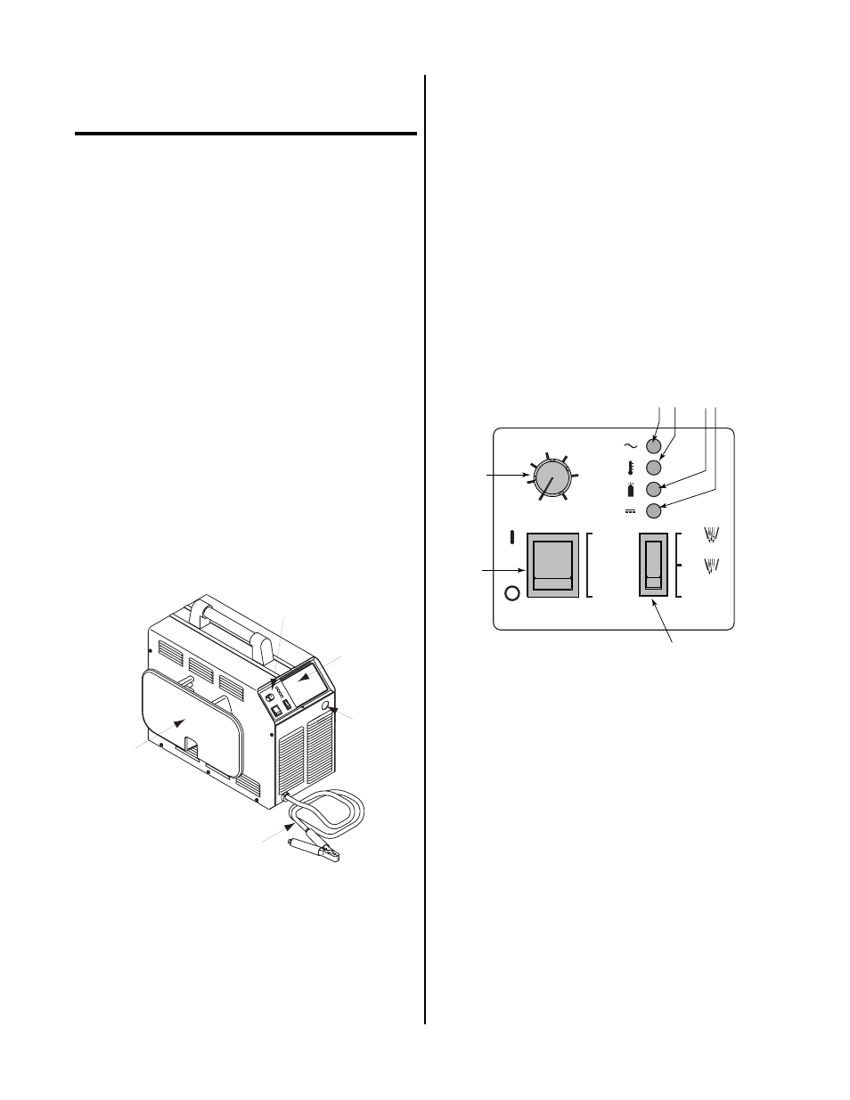
B. Control Panel
CURRENT
TEMP
AC
GAS
DC
LATCH
SET
RUN
ON
OFF
1
2
3
4 5
6 7
A
15
25
35
45
55
65
80
A-02457
Figure 4-2 Operating Controls
1. Current Control
Adjustment to set the desired output current between
15-80 amps. For drag cutting applications set the con-
trol between 15 - 35 amps. The unit has an automatic
fold-back circuit that limits current to 35 amps dur-
ing drag cutting.
2. ON/OFF Power Switch
ON position supplies AC power to activate all sys-
tem control circuits. OFF position deactivates control
circuits.