4t.06 mechanized torch operation, 4t.06 mechanized torch operation t-7, Cutmaster 35mm, 40mm – Tweco CutMaster 35mm 40mm User Manual
Page 39
CUTMASTER 35mm, 40mm
Manual 0-5118 4T-7 OPERATION
Torch Travel Speed
NOTE
Refer to Appendix Pages for additional
information as related to the Power Supply
used.
Optimum torch travel speed is dependent on cur-
rent setting, lead angle, and mode of operation
(hand or machine torch).
Current Setting
Current settings depend on torch travel speed,
mode of operation (hand or machine torch), and
the amount of material to be removed.
Pressure Setting
Even though the setting is within the specified
range, if the torch does not pilot well the pressure
may need to be reduced.
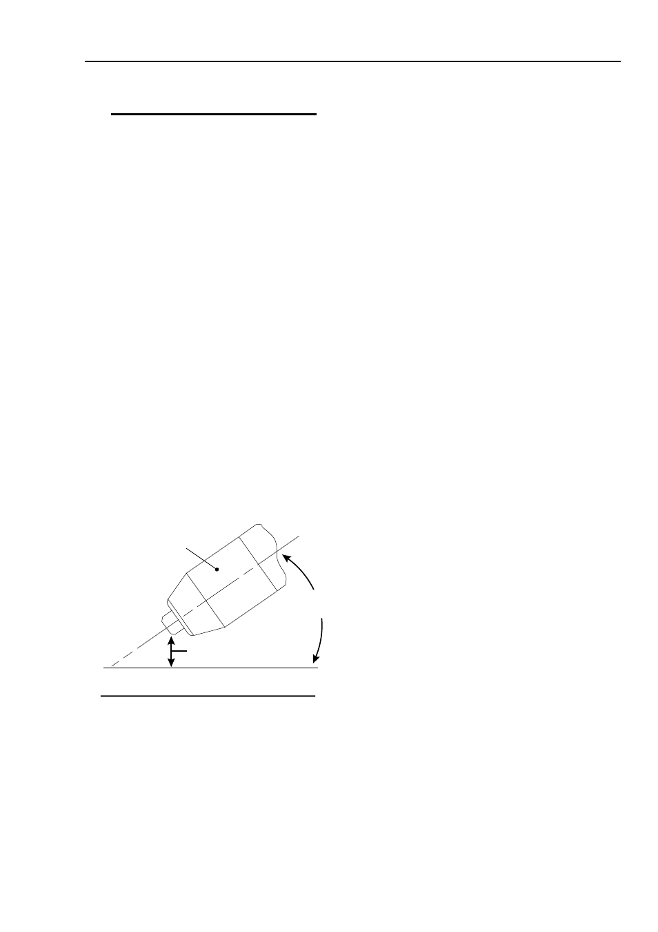
Lead Angle
The angle between the torch and workpiece de-
pends on the output current setting and torch
travel speed. The recommended lead angle is
35°. At a lead angle greater than 45° the molten
metal will not be blown out of the gouge and may
be blown back onto the torch. If the lead angle
is too small (less than 35°), less material may be
removed, requiring more passes. In some appli-
cations, such as removing welds or working with
light metal, this may be desirable.
35°
Workpiece
Torch Head
Standoff Height
A-00941_AB
Gouging Angle and Standoff Distance
Standoff Distance
The tip to work distance affects gouge quality and
depth. Standoff distance of 1/8 - 1/4 inch (3 - 6
mm) allows for smooth, consistent metal removal.
Smaller standoff distances may result in a sever-
ance cut rather than a gouge. Standoff distances
greater than 1/4 inch (6 mm) may result in mini-
mal metal removal or loss of transferred main arc.
Slag Buildup
Slag generated by gouging on materials such as
carbon and stainless steels, nickels, and alloyed
steels, can be removed easily in most cases. Slag
does not obstruct the gouging process if it accumu-
lates to the side of the gouge path. However, slag
build - up can cause inconsistencies and irregular
metal removal if large amounts of material build
up in front of the arc. The build - up is most often
a result of improper travel speed, lead angle, or
standoff height.
4T.06 Mechanized Torch Operation
Cutting With Mechanized Torch
The mechanized torch can be activated by remote
control pendant or by a remote interface device
such as CNC.
1. To start a cut at the plate edge, position
the center of the torch along the edge of
the plate.
Travel Speed
Proper travel speed is indicated by the trail of the
arc which is seen below the plate. The arc can be
one of the following:
1. Straight Arc
A straight arc is perpendicular to the workpiece
surface. This arc is generally recommended
for the best cut using air plasma on stainless
or aluminum.
2. Leading Arc
The leading arc is directed in the same direc-
tion as torch travel. A five degree leading arc
is generally recommended for air plasma on
mild steel.
3. Trailing Arc
The trailing arc is directed in the opposite direc-
tion as torch travel.