Step 9 — wire field controls, Fig. 29 — typical accessory wiring – Carrier AQUAZONE PSV User Manual
Page 27
27
Step 9 — Wire Field Controls
THERMOSTAT CONNECTIONS — The thermostat should
be wired directly to the ECM control board. See Fig. 27.
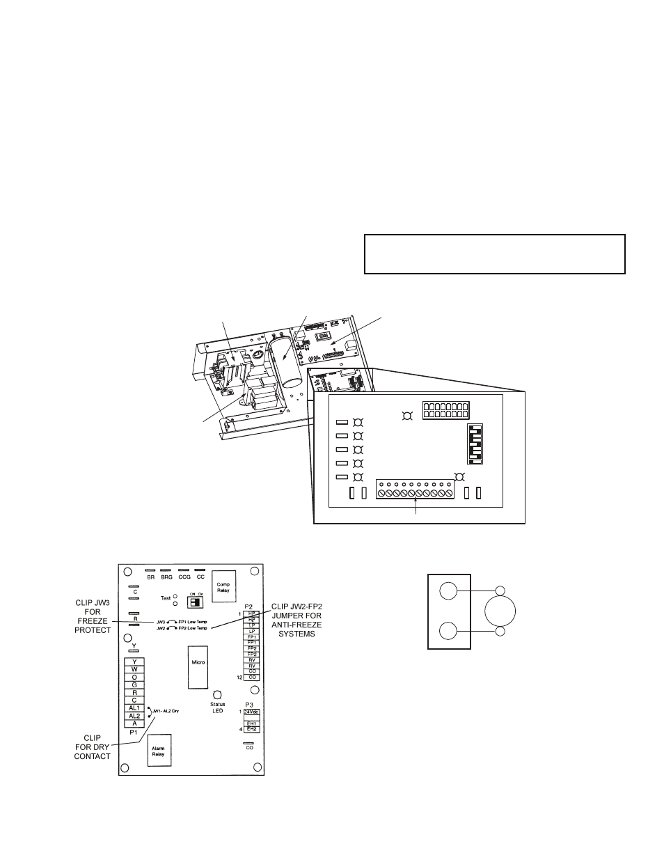
WATER FREEZE PROTECTION — The Aquazone™ con-
trol allows the field selection of source fluid freeze protection
points through jumpers. The factory setting of jumper JW3
(FP1) is set for water at 30 F. In earth loop applications, jumper
JW3 should be clipped to change the setting to 10 F when us-
ing antifreeze in colder earth loop applications. See Fig. 28.
NOTE: The extended range option should be selected
with water temperatures below 60 F to prevent internal
condensation.
AIR COIL FREEZE PROTECTION — The air coil freeze
protection jumper JW2 (FP2) is factory set for 30 F and should
not need adjusting.
ACCESSORY CONNECTIONS — Terminal A on the control
is provided to control accessory devices such as water valves,
electronic air cleaners, humidifiers, etc. This signal operates
with the compressor terminal. See Fig. 29. Refer to the specific
unit wiring schematic for details.
NOTE: The A terminal should only be used with 24-volt
signals — not line voltage signals.
WATER SOLENOID VALVES — An external solenoid
valve(s) should be used on ground water installations to shut
off flow to the unit when the compressor is not operating. A
slow closing valve may be required to help reduce water
hammer. Figure 29 shows typical wiring for a 24-vac external
solenoid valve. Figures 30 and 31 illustrate typical slow closing
water control valve wiring for Taco 500 Series and Taco ESP
Series valves. Slow closing valves take approximately 60 sec.
to open (very little water will flow before 45 sec.). Once fully
open, an end switch allows the compressor to be energized
(only on valves with end switches). Only relay or triac based
electronic thermostats should be used with slow closing valves.
When wired as shown, the slow closing valve will operate
properly with the following notations:
1. The valve will remain open during a unit lockout.
2. The valve will draw approximately 25 to 35 VA through
the “Y” signal of the thermostat.
IMPORTANT: Connecting a water solenoid valve can
overheat the anticipators of electromechanical thermo-
stats. Only use relay based electronic thermostats.
Fig. 27 — Low Voltage Field Wiring
COMPLETE C CONTROL
CAPACITOR
LINE
LO
AD
COMPRESSOR CONTACTOR
TRANSFORMER
Y
GGGG
R
W
O
Y2
Y1
G
R
C
Y2 Y1 G
O W C R DH AL1 A
A
AL1
SW1
SW2
SW3
SW4
SW5
SW6
SW7
SW8
SW9
OFF
ON
G DEHUM
CFM
TB1
J1
S1
THERMOSTAT CONNECTION
TYPICAL
WATER
VALVE
C
A
24 VAC
TERMINAL STRIP P2
Fig. 29 — Typical Accessory Wiring
A50-6269
AQUAZONE CONTROL (Complete C Shown)
Fig. 28 — Typical Aquazone™ Control Board
Jumper Locations
A50-7764
a50-8197