Cleaning, Dip switch settings – tekmar 667 Snow Detector & Melting Control Installation User Manual
Page 18
18 of 32
©
2009 D
667
-
03/09
System Pump (System Pmp 2)
If a pump is connected to the System Pmp 2 terminals (17 and 18), make sure power to the pump circuit is off and install a
jumper between the System Pmp 2 terminals (17 and 18). When the circuit is powered up, the pump should turn on. If no
response occurs, check the wiring between the terminal and the pump and refer to any installation or troubleshooting
information supplied with the pump. If the pump operates properly, disconnect the power and remove the jumper.
Boiler
If the boiler circuit is connected to the Boiler terminals (19 and 20), make sure power to the boiler circuit is off, and install
a jumper between the terminals. When the boiler circuit is powered up, the boiler should fire. If the boiler does not turn
on, refer to any installation or troubleshooting information supplied with the boiler. (The boiler may have a flow switch
that prevents firing until the boiler pump is running). If the boiler operates properly, disconnect the power and remove the
jumper.
Melting
If a device is connected to the Melting terminals (21 and 22), make sure power to the circuit is off, and install a jumper
between the terminals. When the circuit is powered up, the device should operate. If the device does not operate, refer
to any installation or troubleshooting information supplied with the device. If the device operates properly, disconnect the
power and remove the jumper.
Variable Speed Injection Pump
If a variable speed injection pump circuit is connected to the Var and Com terminals (1 and 2), make sure the power to the
terminal block is off and install a jumper between the Var and Com terminals (1 and 2). When the variable speed pump
circuit is powered up, the variable speed pump should operate at full speed. If the pump does not operate, check the
wiring between the terminal block and the pump and refer to any installation or troubleshooting information supplied with
22
23
Sys
P1
25
21
Melting
Power
L
N
24
Cleaning
The control’s exterior can be cleaned using a damp cloth. Moisten cloth with water and wring out prior to wiping control. Do no use
solvents or cleaning solutions.
DIP Switch Settings
The DIP switch settings on the control are very important and should be set to the appropriate
settings prior to making an adjustments to the control through the User Inter-face. The DIP
switch settings change the items that are available to be viewed and / or adjusted in the User
Interface.
If a DIP switch is changed while the control is powered up, the control responds to the change
in setting by returning the display to the VIEW menu. This is true for all the DIP switches
except for the Lock / Unlock DIP switch.
Idle Demand
Melt Demand
the pump. If the pump operates properly, disconnect the power and
remove the jumper.
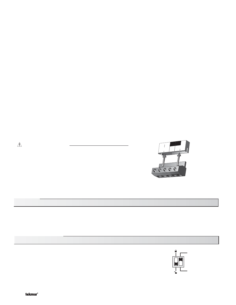
Connecting The Control
Make sure all power to the devices and terminal blocks is off, and
remove any remaining jumpers from the terminals.
Reconnect the terminal blocks to the control by carefully aligning
them with their respective headers on the control, and then pushing
the terminal blocks into the headers. The terminal blocks should snap
fi rmly into place.
Install the supplied safety dividers between the unpowered sensor
inputs and the powered wiring chambers.
Apply power to the control. The operation of the control on power up is
described in the Sequence of Operation section of the brochure.