tekmar 667 Snow Detector & Melting Control Installation User Manual
Page 14
14 of 32
©
2009 D
667
-
03/09
Installation
CAUTION
Improper installation and operation of this control could result in damage to the equipment and possibly even personal injury. It is your
responsibility to ensure that this control is safely installed to all applicable codes and standards. This electronic control is not intended
for use as a primary limit control. Other controls that are intended and certifi ed as safety limits must be placed into the control circuit.
Do not open the control. Refer to qualifi ed personnel for servicing. Opening voids warranty and can result in damage to the equipment
and possibly even personal injury.
STEP ONE
–––––––––––
GETTING READY
Check the contents of this package. If any of the contents listed are missing or damaged, please contact your wholesaler or tektra
sales representative for assistance.
Type 667 includes:
One Snow Detector & Melting Control 667, One Outdoor Sensor 070, Three Universal Sensors 082, Data
Brochures D 667, D 070, D 001, User Brochure U 667, Application Brochure A 667, Essay E 021.
Note: Carefully read the details of the Sequence of Operation to ensure that you have chosen the proper control for
your application.
STEP TWO
––––––––––
MOUNTING THE BASE
Remove the control from its base by pressing down on the release clip in the wiring chamber and sliding the control away from it.
The base is then mounted in accordance with the instructions in the Data Brochure D 001.
STEP THREE
–––––––––
ROUGH-IN WIRING
All electrical wiring terminates in the control base wiring chamber. The base has standard 7/8” (22 mm) knockouts which accept
common wiring hardware and conduit fittings. Before removing the knockouts, check the wiring diagram and select those sections
of the chamber with common voltages. Do not allow the wiring to cross between sections as the wires will interfere with safety
dividers which should be installed at a later time.
•
Power must not be applied to any of the wires during the rough-in wiring stage.
•
All wires are to be stripped to a length of 3/8” (9mm) to ensure proper connection to the control.
• Install the Outdoor Sensor 070, Boiler Sensor 082 and Mixing Sensor(s) 082 according to the installation instructions in the Data
Brochure D 070 and run the wiring back to the control.
• Install the Snow / Ice Sensor 090 according to the installation instructions in the Data Brochure D 090 and run the wiring back
to the control. See Data Brochure D 090 for very important details on sensor location and installation.
• If a Slab Sensor is used, install the slab sensor according to the installation instructions in the Data Brochure D 079 and run the
wiring back to the control. See page 11 for very important details on sensor location and installation.
• If a Remote Display Module (RDM) 040 is used, install the RDM according to the installation instructions in the Data Brochure
D 040 and run the wiring back to the control.
• If a Remote Start / Stop Module 039 is used, install the module according to the installation instructions in the Data Brochure
D 039 and run the wiring back to the control.
• Run wire from other system components (pumps, boiler, etc.) to the control.
• Run wires from the 115 V (ac) power to the control. Use a clean power source with a minimum 15 A circuit to ensure proper
operation. Multi-strand 16 AWG wire is recommended for all 115 V (ac) wiring due to its superior flexibility and ease of installation
into the terminals.
STEP FOUR
––––––––––
ELECTRICAL CONNECTIONS TO THE CONTROL
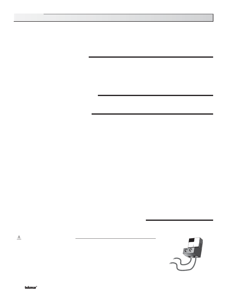
The installer should test to confirm that no voltage is present at any of the wires. Push the control into the base and slide it down
until it snaps firmly into place.
24
25
115 V (ac)
L
N
Power
L
N
Powered Input Connections
115 V (ac) Power
Connect the 115 V (ac) power supply to the Power L and Power N terminals (24 and 25). This
connection provides power to the microprocessor and display of the control. As well, this
connection provides power to the Sys P1 terminal (23) from the Power L terminal (24).