tekmar 667 Snow Detector & Melting Control Installation User Manual
Page 16
16 of 32
©
2009 D
667
-
03/09
13
Com
14
Out
Sensor and Unpowered Input Connections
Do not apply power to these terminals as this will damage the
control.
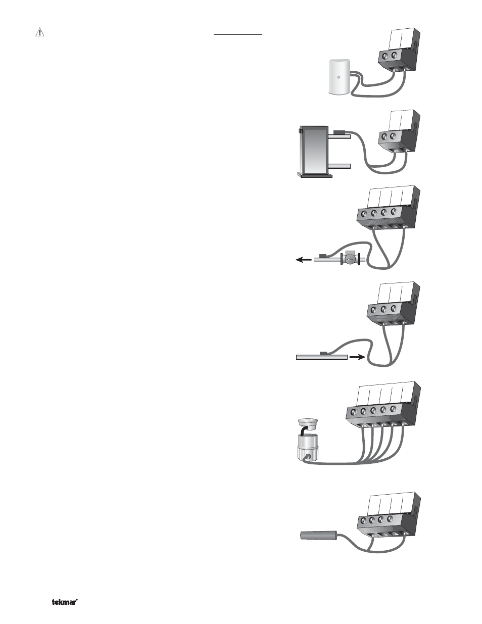
Outdoor Sensor
Connect the two wires from the Outdoor Sensor 070 to the Com and
Out terminals (13 and 14). The outdoor sensor is used by the 667 to
measure the outdoor air temperature.
Boiler Sensor
Connect the two wires from the Boiler Sensor 082 to the Boil and
Com terminals (8 and 9). The boiler sensor is used by the 667 to
measure the water temperature of the boiler.
Mixing Supply Sensor
Connect the two wires from the Mixing Supply Sensor 082 to the
Mix Sup and Com terminals (12 and 9). The mixing supply sensor is
used by the 667 to measure the fluid supply temperature after the
mixing device. Normally the sensor is attached downstream of the
system pump.
Mixing Return Sensor
Connect the two wires from the Mixing Return Sensor 082 to the
Com and Mix Ret terminals (9 and 11). The mixing return sensor is
used by the 667 to measure the fluid return temperature from the
snow melting slab.
EITHER: Snow / Ice Sensor 090
Connect the red wire from the sensor cable to the Red terminal
(3), connect the black wire from the sensor cable to the Blk
terminal (4), connect the blue wire from the sensor cable to the Blu
terminal (5), connect the yellow wire from the sensor cable to the
Yel terminal (6) and connect the brown wire from the sensor cable to
the Brn / Slab terminal (7). The snow / ice sensor is used by the 667 to
measure the slab surface temperature. This sensor must be installed
flush with the slab surface and 1/2 way between the heating pipes.
See Data Brochure D 090 for installation instructions regarding the
Snow / Ice Sensor 090 and Sensor Socket 091.
OR: Slab Sensor
If a Snow / Ice Sensor 090 is not used, a slab sensor can be used.
If a slab sensor is used, connect the two wires from the slab sensor
to the Blk and Brn / Slab terminals (4 and 7). The slab sensor is used
by the 667 to measure the slab temperature.
Note: Proper sensor placement is critical for correct operation of the
667 control. The slab sensor must be installed 1/2 way between the
heating pipes and 1’’ (25 mm) below the surface of the slab. Although
the sensor can be installed directly into the slab, we recommend
that the sensor be installed in tubing or conduit in such a manner
that the sensor can be removed and replaced in case of failure.
8 9
Com
Boil
Boiler
Sensor
10
tN2
11
Mix
Ret
12
Mix
Sup
9
Com
Mix Supply
Sensor
System
Pump
9
Com
10
tN2
11
Mix
Ret
Mix Return
Sensor
3
Red
4
Blk
5
Blu
6
Yel
7
Brn/
Slab
5
4
6
7
Blk
Blu Yel
Brn/
Slab
OR