tekmar 665 Snow Detector & Melting Control Installation User Manual
Page 9
9
of
28
©
2012 D
665
-
04/12
Snow / Ice Sensor 090
The slab temperature is displayed as SLAB in the VIEW menu. This temperature is calculated from the edge and center sensors
built into the 090.
SLAB TARGET TEMPERATURE (SLB TRG)
The SLAB TRG temperature is determined from the Melting setting, or Idle setting and the outdoor air temperature. The control
displays the temperature that it is currently trying to maintain at the slab sensor. If the control does not presently have a requirement
for heat, it displays “– – –“ in the STATUS item while in the VIEW menu.
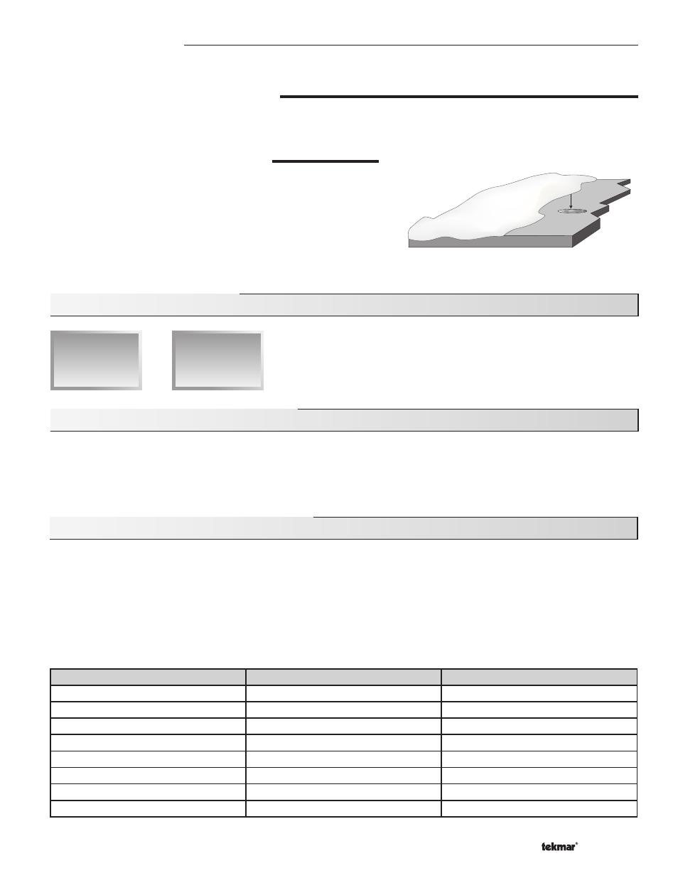
Dry
Snow Ice Sensor
Section E: Idling Operation
Section E1
General Idling
Operation
Section E1: General Idling Operation
When the snow melting system starts from a cold temperature, the time required for the system to reach the melting temperature
may be excessive. To decrease this start up time, the 665 has an idling feature which can maintain the zone at a lower temperature.
This feature is also useful for preventing frost and light ice formation. The IDLING setting in the ADJUST menu sets the slab surface
temperature while the control is in the idling mode. When in the idling mode, IDLE is displayed in the STATUS item of the VIEW menu.
If idling is not desirable, the IDLING setting may be set to OFF.
The temporary idle allows the control to enter the idle state for a set amount of time. If the snow ice detector does not detect snow
during the temporary idle period, the control then leaves the idle state and returns to the OFF state. This is useful in applications
where there is the possibility of snow and the slab can be pre-heated in order to have a short heat up time if snow is detected.
To enable a temporary idle, the Temporary Idle setting in the ADJUST menu must be set from OFF to the length of the temporary idle.
The DIP Switch must be set to IDLE DEMAND and the IDLING must be set to a temperature. To activate a temporary idle, a voltage
between 24 and 240 V (ac) must be applied across the Melt/Idle Demand terminals for at least 4 seconds.
When a Temporary Idle time is selected, the control has three available states: OFF, Temporary Idle, and Melting. The table below
describes the action of the control:
Section E2
Temporary
Idle
Section E2: Temporary Idle (TMPY IDL)
Control State
Action
Result
OFF
External Idle Demand
Temporary Idle
OFF
Manual or Auto Melt Start
Melting
Melting
External Idle Demand
Melting
Melting
Manual or Auto Melt Start
Melting
Melting
Manual or Auto Melt Stop
OFF
Temporary Idle
Temporary Idle Expires
OFF
Temporary Idle
Manual or Auto Melt Start
Melting
Temporary Idle
Manual Melt Stop
OFF
ADDITIONAL MELTING TIME (ADD MELT)
In cases where areas of the snow melting system haven’t completely
melted after the melting mode has finished and the 090 is dry, the 665
has a function in which additional time can be added to melt the zone.
This is an adjustable time through the ADD MELT item in the ADJUST
menu of the control. The ADD MELT time is calculated into a running
time and is displayed in the STATUS item while in the VIEW menu. Once
the 090 becomes dry and the slab temperature is at least the slab target
temperature, the ADD MELT time starts counting down.