tekmar 665 Snow Detector & Melting Control Installation User Manual
Page 13
13 of 28
©
2012 D
665
-
04/12
9 10
Melt / Idle
Demand
24 to 240 V (ac)
N
L
Melt / Idle Demand
To generate a melt demand or idle demand, a voltage
between 24 V (ac) and 240 V (ac) must be applied across the
Melt / Idle Demand terminals (9 and 10).
Output Connections
System Pump Contact (Sys P1)
The Sys P1 output terminal (15) on the 665 is a powered output.
When the relay in the 665 closes, 115 V (ac) is provided to the Sys P1
terminal (15) from the Power L terminal (16). To operate the system
pump, connect one side of the system pump circuit to terminal and
the second side of the pump circuit to the neutral (N) side of the 115
V (ac) power supply.
Melting Contact
The Melting terminals (11 and 12) are an isolated output in the 665.
There is no power available on these terminals from the control. These
terminals are used as a switch to make or break an external circuit.
Sensor and Unpowered Input Connections
Do not apply power to these terminals as this will damage the
control.
Outdoor Sensor
Connect the two wires from the Outdoor Sensor 070 to the Out and
Com terminals (6 and 7). The outdoor sensor is used by the 665 to
measure the outdoor air temperature.
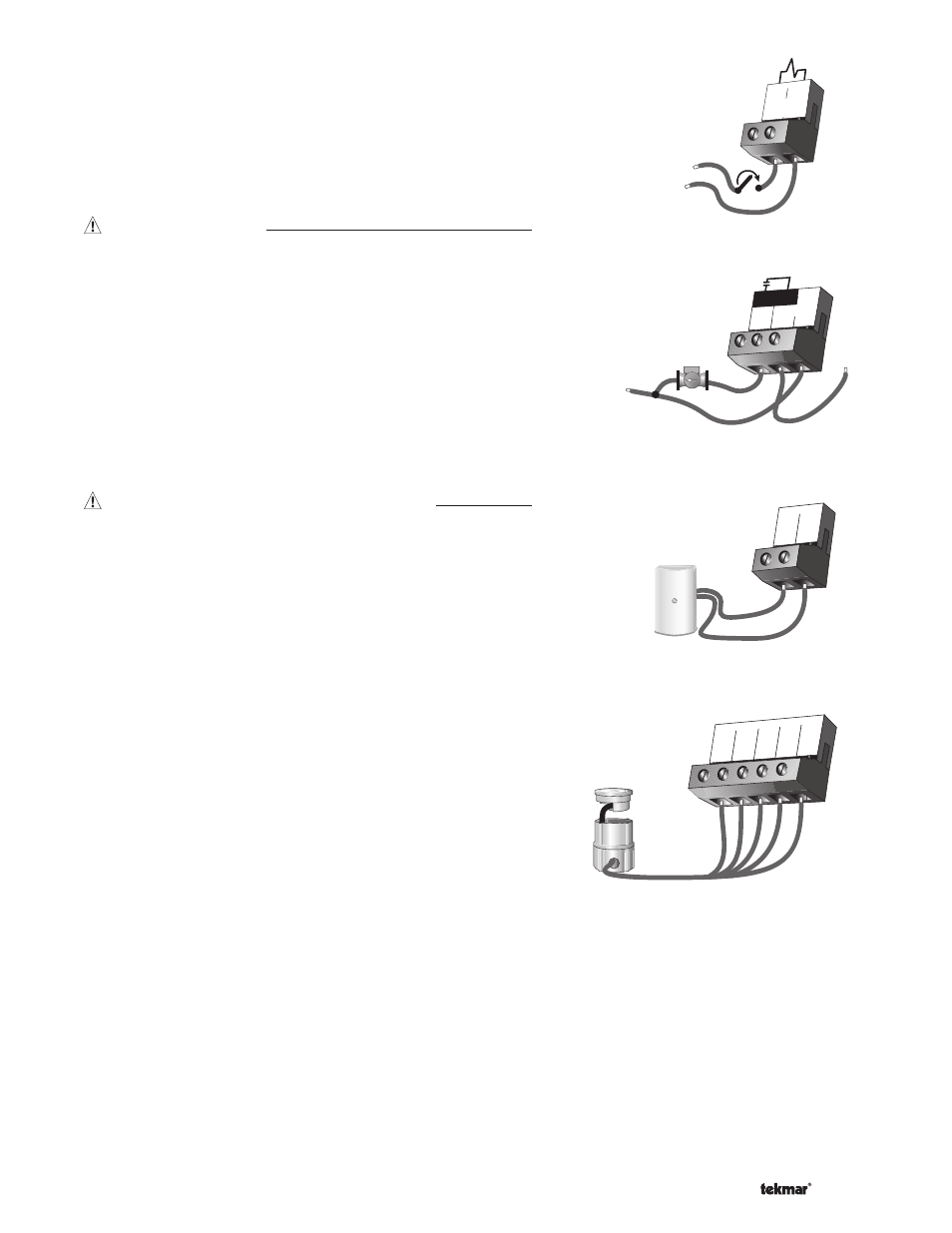
EITHER: Snow / Ice Sensor 090
Connect the red wire from the sensor cable to the Red terminal (1),
connect the black wire from the sensor cable to the Blk terminal (2),
connect the blue wire from the sensor cable to the Blu terminal (3),
connect the yellow wire from the sensor cable to the Yel terminal
(4) and connect the brown wire from the sensor cable to the
Brn / Slab terminal (5). The snow / ice sensor is used by the 665 to
measure the slab surface temperature of the zone. This sensor must
be installed flush with the slab surface and 1/2 way between the
heating pipes. See Data Brochure D 090 for installation instructions
regarding the Snow / Ice Sensor 090 and Sensor Socket 091
Sys
P1
115 V (ac)
N
L
Power
17
L
N
16
15
6
Com
7
Out
1
Red
2
Blk
3
Blu
4
Yel
5
Brn/
Slab
OR: Slab Sensor
If a Snow / Ice Sensor 090 is not used, a slab sensor can be used. If a slab sensor is used, connect the two wires from the
slab sensor to the Blk and Brn / Slab terminals (2 and 5). The slab sensor is used by the 665 to measure the slab temperature
of the zone.
Note: Proper sensor placement is critical for correct operation of the 665 control. The slab sensor must be installed 1/2 way
between the heating pipes and 1’’ (25 mm) below the surface of the slab. Although the sensor can be installed directly into the
slab, we recommend that the sensor be installed in tubing or conduit in such a manner that the sensor can be removed and
replaced in case of failure.