tekmar 665 Snow Detector & Melting Control Installation User Manual
Page 10
10 of 28
©
2012 D
665
-
04/12
Installation
CAUTION
Improper installation and operation of this control could result in damage to the equipment and possibly even personal injury. It is your
responsibility to ensure that this control is safely installed to all applicable codes and standards. This electronic control is not intended
for use as a primary limit control. Other controls that are intended and certifi ed as safety limits must be placed into the control circuit.
Do not open the control. Refer to qualifi ed personnel for servicing. Opening voids warranty and can result in damage to the equipment
and possibly even personal injury.
STEP ONE
–––––––––––
GETTING READY
Check the contents of this package. If any of the contents listed are missing or damaged, please contact your wholesaler or tekmar
sales representative for assistance.
Type 665 includes:
One Snow Detector & Melting Control 665, One Outdoor Sensor 070, Data Brochures D 665, User Brochure
U 665, and Application Brochure A 665.
Note: Carefully read the details of the Sequence of Operation to ensure that you have chosen the proper control for
your application.
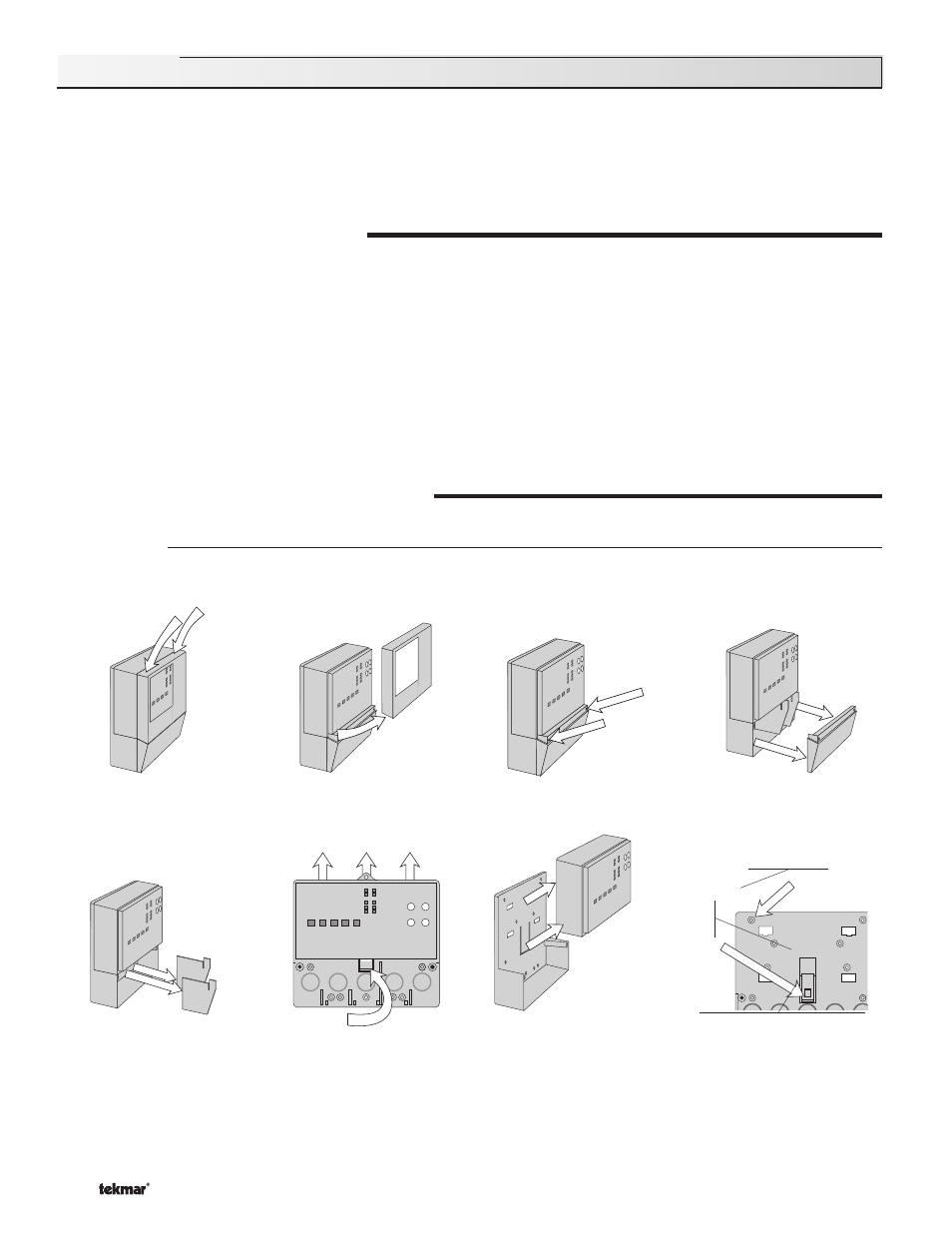
Enclosure A
Enclosure A is a robust housing for the control and associated wiring. Safety dividers in the wiring chamber are provided to
separate low and high voltage wiring.
Press down at the fi ngertip grips
on top of the front cover and pull
out and down.
Lift the front cover up and away
from the control.
Loosen the screws at the front
of the wiring cover.
The wiring cover pulls straight out
from the wiring chamber.
The base is ready for mounting.
The control lifts up and away
from the base.
Press the control release clip
on the base inside the wiring
chamber and slide the control
upwards.
Remove the safety dividers
from the wiring chamber by
pulling them straight out of their
grooves.
There are 10 conduit knock-outs at the back
and bottom of the wiring chamber.
13 Mounting holes
Control
release
clip
Control release clip
STEP TWO
–––––––––––
CONTROL INSTALLATION