tekmar 665 Snow Detector & Melting Control Installation User Manual
Page 15
15 of 28
©
2012 D
665
-
04/12
Heat Contact
If a zone pump or zone valve is connected to Heat terminals (11 and 12), make sure power to the pump or valve circuit is off and
install a jumper between the Heat terminals (11 and 12). When the circuit is powered up, the zone pump should turn on or the
valve should open completely. If no response occurs, check the wiring between the terminal and the pump or valve and refer
to any installation or troubleshooting information supplied with these devices.
Melting
If a device is connected to the Melting terminals (13 and 14), make sure power to the circuit is off, and install a jumper
between the terminals. When the circuit is powered up, the device should operate. If the device does not operate, refer to
any installation or troubleshooting information supplied with the device. If the device operates properly, disconnect the power
and remove the jumper.
Connecting The Control
Make sure all power to the devices and terminal blocks is off, and
remove any remaining jumpers from the terminals.
Reconnect the terminal blocks to the control by carefully aligning
them with their respective headers on the control, and then pushing
the terminal blocks into the headers. The terminal blocks should
snap firmly into place.
Install the supplied safety dividers between the unpowered sensor
inputs and the powered wiring chambers.
Apply power to the control. The operation of the control on power up
is described in the Sequence of Operation section of the brochure.
14
15
Sys
P1
17
13
Melting
Power
L
N
16
17
Power
16
V
103.5 to 126.5 V (ac)
N
L
20 to 260 V (ac)
10
9
Melt/Idle
Demand
15 16
17
Sys
P1
Power
N
L
115 V (ac)
N
L
Test The Power Supply
Make sure exposed wires and bare terminals are not in con-
tact with other wires or grounded surfaces. Turn on the power and
measure the voltage between the Power L and Power N terminals
(16 and 17) using an AC voltmeter, the reading should be between
103.5 and 126.5 V (ac).
Test The Powered Inputs
Melt / Idle Demand
If a Melt/Idle demand is used, measure the voltage between the
Melt/Idle Demand terminals (9 and 10). When the melting or idling
device calls for heat, you should measure between 20 and 260 V (ac)
at the terminals. When the melting or idling device is off, you should
measure less than 5 V (ac).
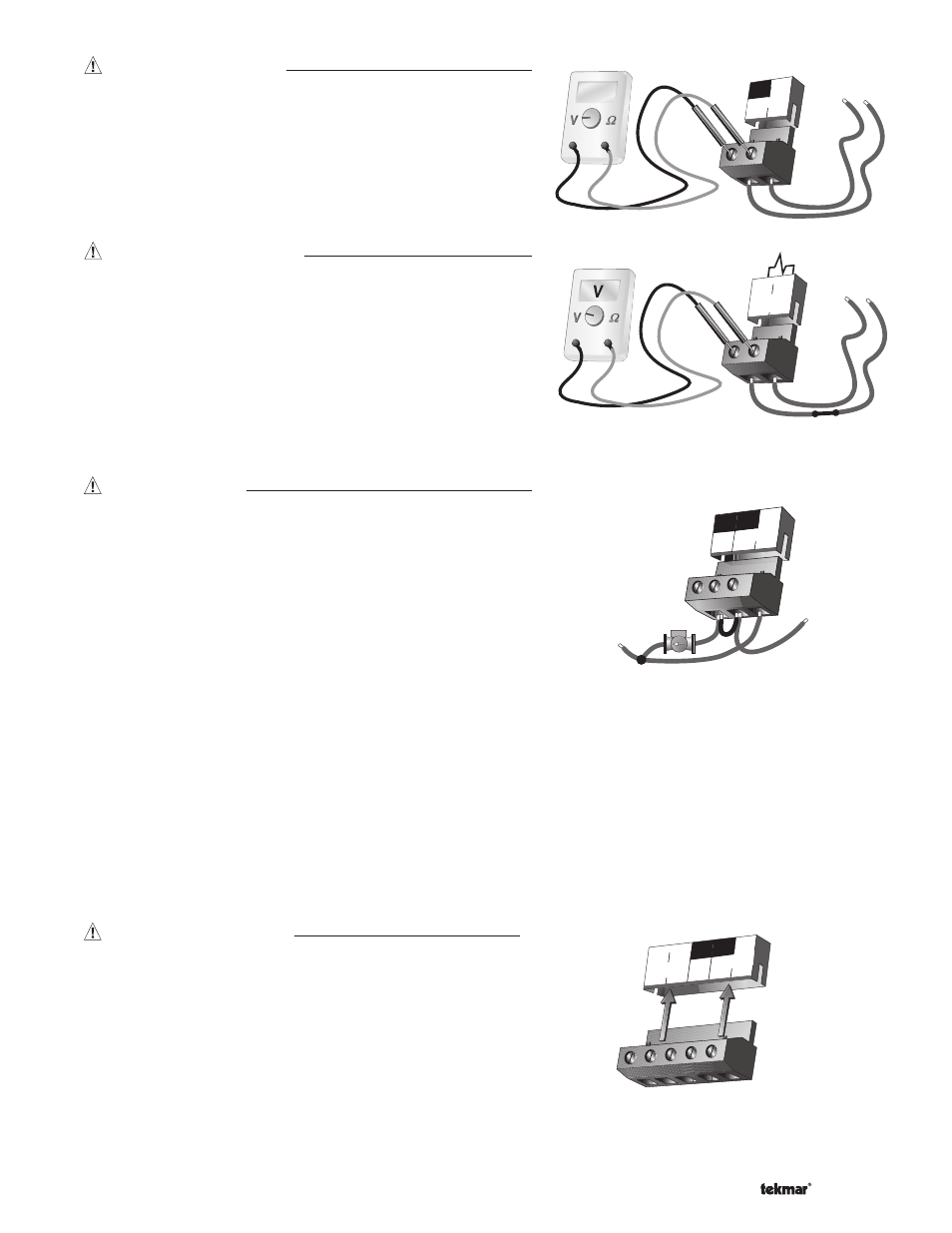
Test The Outputs
System Pump (Sys P1)
If a system pump is connected to the Sys P1 terminal (15), make
sure that power to the terminal block is off and install a jumper
between the Sys P1 and Power L terminals (15 and 16). When
power is applied to the Power L and Power N terminals (16 and
17), the system pump should start. If the pump does not turn on,
check the wiring between the terminal block and pump and refer
to any installation or troubleshooting information supplied with the
pump. If the pump operates properly, disconnect the power and
remove the jumper.