tekmar 545 Thermostat Installation User Manual
Page 28
© 2008
D 545 - 07/08
28 of 40
Room Sensor Only
When operating with only an air sensor, the on times for
the Heat 1 and Heat 2 relays are calculated to satisfy the
requirements of the room sensor.
Floor Sensor Only
When operating with only a floor sensor, the on times for
the Heat 1 and Heat 2 relays are calculated to satisfy the
requirements of the floor sensor. The thermostat operates
to maintain the floor at the minimum floor temperature
setting.
Note: Operating with only a floor sensor can lead to either
overheating or underheating of the space.
Room and Floor Sensor
When operating with both room and floor sensors, the
thermostat calculates an on time for the Heat 1 relay to
satisfy the floor sensor’s requirements and on times for
the Heat 1 and Heat 2 relays to satisfy the room sensor’s
requirements. The thermostat operates the Heat 1 relay
for the longer of these two on times.
While the minimum floor temperature is satisfied, the on
times of the Heat 1 and Heat 2 relays are calculated to
satisfy the room temperature requirements.
During heavy loads, the maximum floor temperature setting
limits the on time of the Heat 1 relay. In this situation, the
Heat 2 relay may be on while the Heat 1 relay is off.
Note: During light heating loads, overheating can occur
due to the minimum floor temperature requirements.
Zone Group
Heat 1 Pump = OFF
Zone Manager: Zone Group DIP = On
Operated by
Zone Manager
Operated by
tN4 System Control
Heat 1 Pump = On
Zone Manager: Zone Group DIP = OFF
Zone Group
1st
Stage
2nd
Stage
Mix Water Temperature Bus
Boiler Water Temperature Bus
System Pump Operation
When a tN4 System Control is used, each tN4 bus has a
system pump.
•
• If the tN4 bus’s system pump must turn on when the
Heat 1 relay is on, set the H1 Pump setting in the Adjust
menu to On.
•
• If the tN4 bus’s system pump must turn on when the
Heat 2 relay is on, set the H2 Pump setting in the Adjust
menu to On.
Second Stage Heat Source
The tN4 System Control needs to know whether second
stage heating operates a non-hydronic heating system, a
boiler water temperature zone, or a mixed water temperature
zone.
•
• If using non-hydronic, set to None.
•
• If using boiler temperature water, set to Boil.
•
• If using a mix water temperature, enter the correct Mix
bus number.
Thermal Motor Zone Valves
When using a thermal motor zone valve, system pump
operation must be delayed to allow the thermal motor zone
valve to fully open.
•
• When thermal motor zone valves are used set the Heat
1 Delay setting to On.
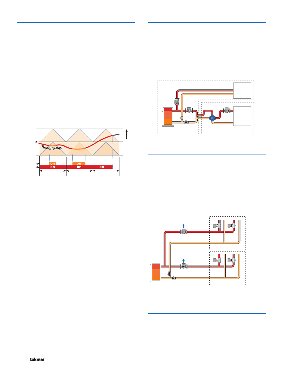
Two-Stage PWM Heating
W
a
rmer
Set
Heat
Cycle Length
Heat 2
Heat 1
Two Stage Heating
The temperature in a two stage zone is controlled by varying
the on time of the Heat 1 and Heat 2 relays during a cycle.
Under light loads, the Heat 1 relay is cycled on and off. As
the load increases, the Heat 1 relay on time is increased
until it reaches the maximum of the cycle length or, if a
floor sensor is used, the slab temperature reaches the floor
maximum setting. The Heat 2 relay is then cycled and its
on time is increased as the load increases.
When the heating load decreases, the on time of the
Heat 2 relay is reduced until the Heat 2 relay is turned off
completely. The thermostat then reduces the on time of
the Heat 1 relay.
Note: When using a floor sensor, the Heat 2 relay may be
on while the Heat 1 relay is off if the floor temperature has
reached the floor maximum setting.