Sensor and unpowered input connections, Outdoor sensor, Boiler sensor – tekmar 364 Universal Reset Control Installation User Manual
Page 19: Mixing supply sensor, Mixing return sensor, Mix 10k sensor, Mixing zone control input, Boiler zone control input, Tekmar net tn2 device
19 of 36
© 2001
D 364 - 07/01
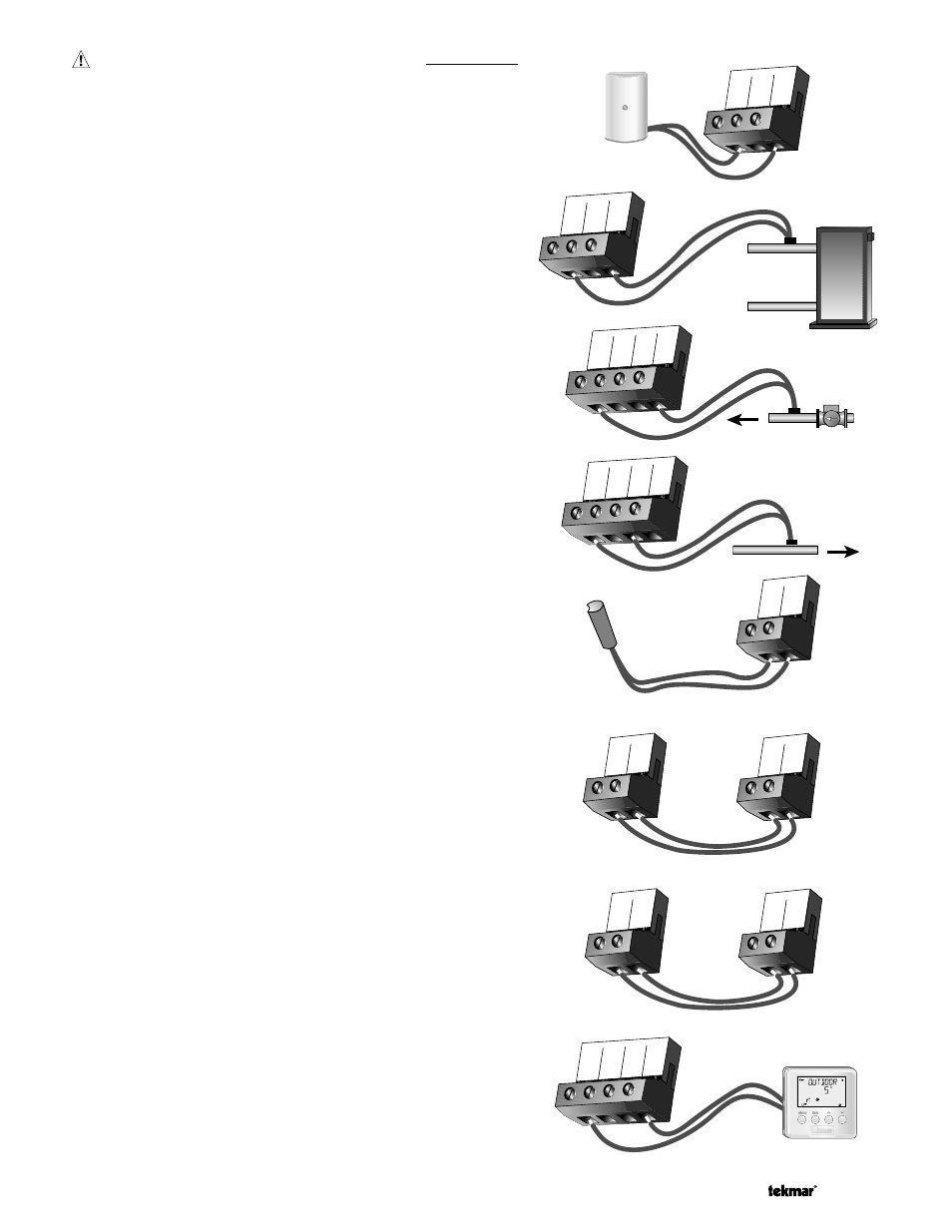
Sensor and Unpowered Input Connections
Do not apply power to these terminals as this will damage the
control.
Outdoor Sensor
Connect the two wires from the Outdoor Sensor 070 to the Com
and Out terminals (27 and 29). The outdoor sensor is used by the
364 to measure the outdoor air temperature.
Boiler Sensor
Connect the two wires from the Boiler Sensor 071 to the Com and
Boil terminals (24 and 26). The boiler sensor is used by the 364
to measure the water temperature of the boiler.
Mixing Supply Sensor
Connect the two wires from the Mixing Supply Sensor 071 to
the Com and Mix Sup terminals (20 and 23). The mixing supply
sensor is used by the 364 to measure the supply temperature
after the mixing device. Normally the sensor is attached down-
stream of the mixing system pump (P3).
Mixing Return Sensor
Connect the two wires from the Mixing Return Sensor 071 to the
Com and Mix Ret terminals (20 and 22). The mixing return sensor
is used by the 364 to measure the fluid return temperature from
the snow melting slab. A mixing return sensor is only used when
the Snow Melting / Mixing Reset DIP switch is set to the Snow
Melting position.
Mix 10K Sensor
Either an indoor sensor, slab sensor, or zone control may be
connected to the Mix 10K input. If a sensor is used, connect the
two wires from the sensor to the Com and Mix 10K terminals
(20 and 21).
Mixing Zone Control Input
If an external tekmar zone control is used for control of mixing
zones, connect the wire from the Com Sen terminal on the zone
control to the Com terminal (20) on the 364. Connect the Zo Out ter-
minal on the zone control to the Mix 10K terminal (21) on the 364.
Note: The wires from the zone control are polarity sensitive. The
communication does not operate correctly if the wires are reversed.
Boiler Zone Control Input
If an external tekmar zone control is used for control of boiler zones,
connect the wire from the Com Sen terminal on the zone control to
the Com terminal (24) on the 364. Connect the Zo Out terminal on
the zone control to the Boil Zo In terminal (25) on the 364.
Note: The wires from the zone control are polarity sensitive. The
communication does not operate correctly if the wires are reversed.
tekmar Net tN2 Device
A Remote Display Module (RDM) 040 or Remote Start / Stop
Module 039 may be connected to the tekmar Net tN2 input. Con-
nect the Com terminal from the 040 or 039 to the Com terminal
(27) on the 364. Connect the tN2 terminal from the 040 or 039 to
the tN2 terminal (30) on the 364.
Note: The wires from the RDM and Remote Start / Stop Module
are polarity sensitive. The 040 or 039 do not operate correctly if
the wires are reversed.
Com
27
DHW
28
Out
29
Com
20
Mix
21
10K
Mix
22
Ret
Mix
23
Sup
Com
24
Boil
25
Zo in
Boil
26
Boiler
Sensor
Com
20
Mix
21
10K
Mix
22
Ret
Mix
23
Sup
Com
20
Mix
21
10K
Zo
Out
Com
Sen
Zone Control
tekmar 364
Com
24
Boil
25
Zo in
Zo
Out
Com
Sen
Zone Control
tekmar 364
Com
20
Mix
21
10K
Com
27
DHW
28
Out
29
tN2
30