tekmar 364 Universal Reset Control Installation User Manual
Page 18
© 2001
D 364 - 07/01
18 of 36
DHW Demand
To generate a DHW demand, a voltage between 24 V (ac) and 240 V (ac) must be
applied across the Setp / DHW and the Com Dem terminals (5 and 4).
Setpoint Demand
To generate a setpoint demand, a voltage between 24 V (ac) and 240 V (ac) must
be applied across the Setp / DHW and the Com Dem terminals (5 and 4).
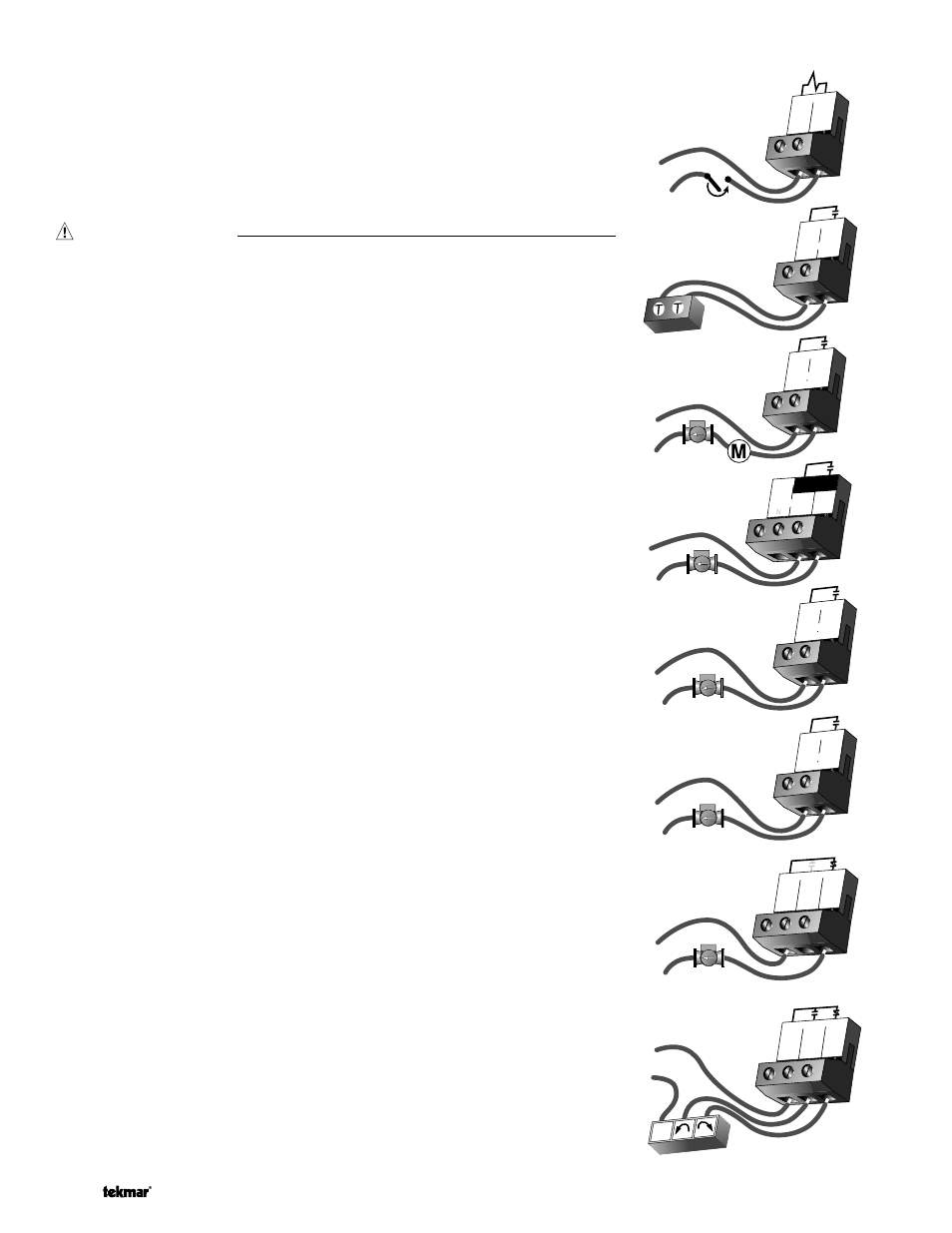
Output Connections
Boiler Contact
The Boiler terminals (15 and 16) are an isolated output in the 364. There is no power
available on these terminals from the control. These terminals are used as a switch
to either make or break the boiler circuit. When the 364 requires the boiler to fire, it
closes the contact between terminals 15 and 16.
DHW Pump / Valve Contact
The DHW Pmp / Vlv terminals (13 and 14) are an isolated output in the 364. There
is no power available on these terminals from the control. These terminals are to be
used as a switch to either make or break power to the DHW pump or DHW valve.
Since this is an isolated contact, it may switch a voltage between 24 V (ac) and 240
V (ac).
Primary Pump Contact (Prim P1)
The Prim P1 output terminal (8) on the 364 is a powered output. When the relay in
the 364 closes, 120 V (ac) is provided to the Prim P1 terminal (8) from the Power L
terminal (7). To operate the primary pump, connect one side of the primary pump
circuit to terminal 8 and the second side of the pump circuit to the neutral (N) side
of the 120 V (ac) power supply.
Boiler System Pump (Boil Sys Pmp P2)
The Boil Sys Pmp P2 terminals (9 and 10) are an isolated output in the 364. There
is no power available on these terminals from the control. These terminals are to be
used as a switch to either make or break power to the boiler system pump. Since
this is an isolated contact, it may switch a voltage between 24 V (ac) and 240 V (ac).
Mixing System Pump (Mix Sys Pmp P3)
The Mix Sys Pmp P3 terminals (11 and 12) are an isolated output in the 364. There
is no power available on these terminals from the control. These terminals are to be
used as a switch to either make or break power to the mixing system pump. Since
this is an isolated contact, it may switch a voltage between 24 V (ac) and 240 V (ac).
Variable Speed Injection Pump
The 364 can vary the speed of a permanent capacitor, impedance protected or
equivalent pump motor that has a locked rotor current of less than 2.4 A. Most small
wet rotor circulators are suitable as described in Essay E 021. The 364 has an inter-
nal overload fuse which is rated at 2.5 A 250 V (ac). Contact your tekmar sales
representative for details on the repair procedures if the fuse is blown.
If a variable speed injection pump is used, connect one of the wires from the vari-
able speed injection pump to the Cls / Var terminal (19) on the 364. Connect the Pwr
Mix terminal (17) to the live (L) side of the 120 V (ac) power source. The other wire
on the variable speed injection pump must be connected to the neutral (N) side of
the 120 V (ac) power supply.
Mixing Valve Actuator
If a mixing valve is used, connect one side of the 24 V (ac) power to the Pwr Mix
terminal (17) on the control. The output relay Opn (18) is then connected to the open
terminal of the actuating motor and the output relay Cls / Var (19) is connected to
the close terminal of the actuating motor. Connect the second side of the 24 V (ac)
circuit to the common terminal of the actuating motor.
15 16
Boiler
DHW
13
Pmp/Vlv
14
24 to 240 V (ac)
or
120 V (ac)
Boil Sys
9
Pmp P2
10
L
N
120 V (ac)
Mix Sys
11
Pmp P3
12
L
N
Pwr
17
Mix
Opn
18
Cls/
19
Var
120 V (ac)
L
N
Pwr
17
Mix
Opn
18
Cls/
19
Var
24 or 120 V (ac)
R
C
Com
6
7
L
Prim
P1
Power
120 V (ac)
L
N
Com
4
Dem
Setp/
5
DHW
24 to 240 V (ac)
8