Boiler differential (boil diff), No boiler sensor, Boiler enable ( 30% enable / 10% enable ) – tekmar 360 Mixing Control User Manual
Page 9
9 of 20
© 2009 D 360 - 03/09
BOILER SENSOR ON THE SUPPLY (Boiler Sensor DIP switch = Supply)
The boiler sensor can be located on the boiler supply if the 360 is the only control that is
operating the boiler. When in the supply mode, the 360 determines the required operating
temperature of the boiler using Boiler Load Reset. With Boiler Load Reset, the 360 oper-
ates the boiler at the lowest possible supply temperature that is sufficient to satisfy the
requirements of the mixing valve. If this mode of operation is selected, the boiler pump
should either operate continuously, or be operated in parallel with the system pump con-
tact (Sys Pmp).
Note: The boiler pump should not be operated by the boiler’s aquastat, as this may lead to
improper cycling of the boiler because of inconsistent flow past the boiler supply sensor.
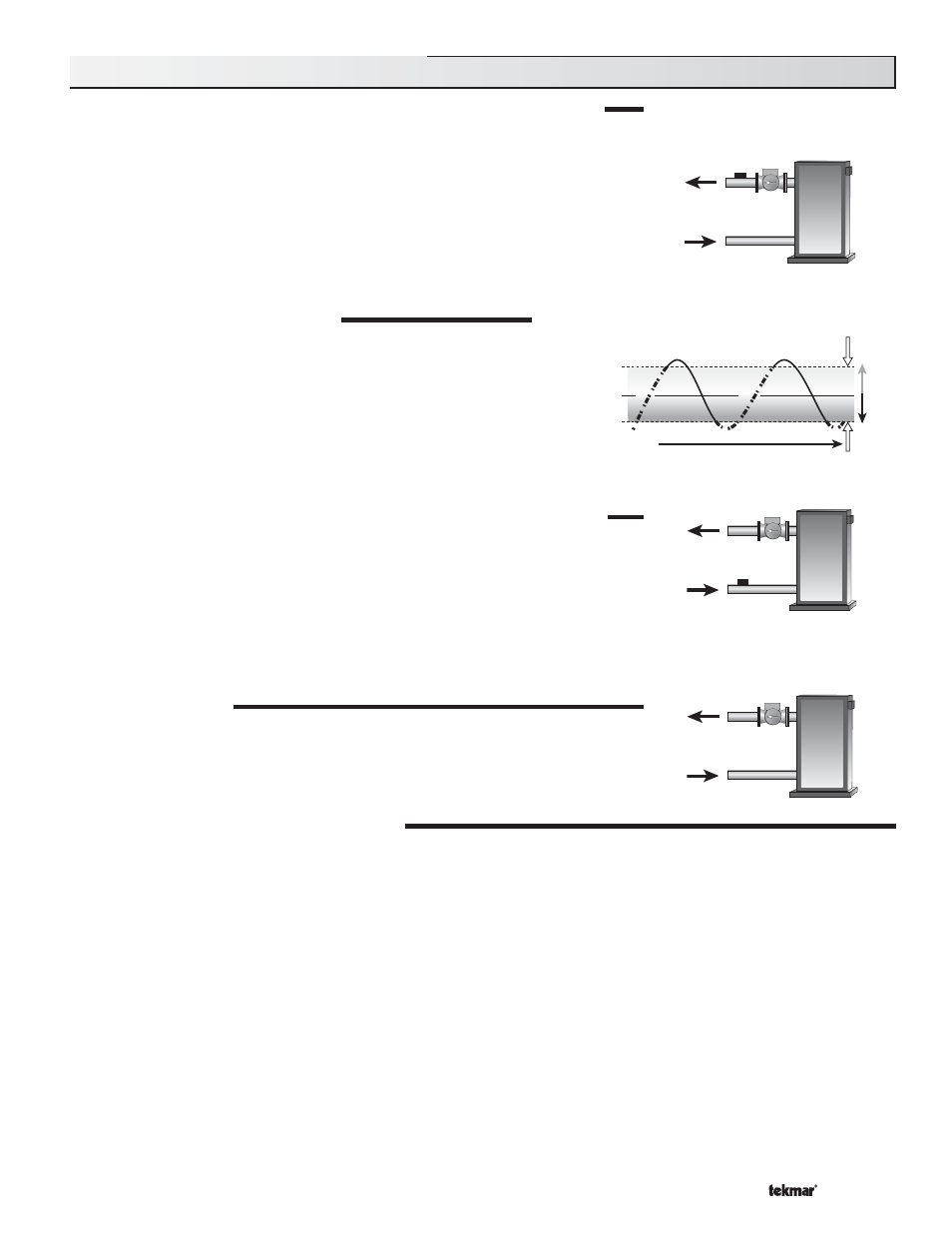
BOILER DIFFERENTIAL (BOIL DIFF)
An on / off heat source such as a boiler must be operated with a differen-
tial in order to prevent short cycling. When the boiler supply temperature
drops below the bottom rail of the differential, the 360 closes the Boiler
contact to fire the boiler. When the boiler supply temperature rises above
the top rail of the differential, the 360 opens the Boiler contact to turn off
the boiler. With the 360, either a fixed or automatic differential setting is
selected. If automatic differential (Ad) is selected, the 360 automatically
adjusts the boiler differential under the current load conditions to avoid
short cycling.
BOILER SENSOR ON THE RETURN (Boiler Sensor DIP switch = Return)
The boiler sensor should be located on the boiler return if the 360 is one of many controls
that can call for boiler operation. When in the return mode, the 360 provides a boiler enable
as described in the BOILER ENABLE section. The 360 no longer tries to control the boiler
supply water temperature directly but allows the boiler to operate at its operating aquastat
setting when required. If this mode of operation is selected, the boiler pump should either
operate continuously or be operated in parallel with the system pump contact (Sys Pmp).
Note: The boiler pump should not be operated by the boiler’s aquastat, as this may lead to
improper cycling of the boiler because of inconsistent flow past the boiler return sensor.
NO BOILER SENSOR
The 360 is capable of operating without a boiler sensor if desired. Without a boiler sensor,
the 360 provides a boiler enable as described in the BOILER ENABLE section, but is
unable to provide boiler protection. This type of application is typical if the 360 is drawing
heat from a heat source that already incorporates some form of boiler protection.
BOILER ENABLE (30% Enable / 10% Enable)
The 360 has a DIP switch that allows for the selection between a 30% boiler enable and a 10% boiler enable. This switch is only
functional when the Boiler Sensor DIP switch is set to Return.
In the 30% position, the 360 closes the Boiler contact when the position of the mixing valve exceeds 30%. The Boiler contact
remains closed until the position of the mixing valve reduces below 15%. This setting would normally be chosen for low mass boil-
ers (copper fin-tube, etc.) or systems with low thermal mass in the loop between the boiler and the mixing valve.
In the 10% position, the 360 closes the Boiler contact when the position of the mixing valve exceeds 10%. The Boiler contact
remains closed until the position of the mixing valve reduces below 5%. This setting is normally chosen for high mass boilers (cast
iron, steel, fire-tube, etc.) or systems with large thermal mass in the loop between the boiler and the mixing valve.
In order to prevent short cycling, the Boiler contact has a minimum on time, and a minimum off time.
Boiler Supply
Sensor
Boiler Return
Sensor
No Boiler
Sensor
B
oi
le
r O
n
B
oi
le
r
O
n
Time
Supply W
a
ter T
e
mper
atur
e
Differential = 10°F (6°C)
165°F (74°C)
160°F (71°C)
155°F (68°C)
Section C2: Boiler Sensor Placement