Sequence of operation – tekmar 360 Mixing Control User Manual
Page 4
© 2009
D 360 - 03/09
4 of 20
Sequence of Operation
POWERING UP THE CONTROL
When the Mixing Control 360 is powered up, the control displays the control type number in the LCD for 2 seconds. Next, the
software version is displayed for 2 seconds. Finally, the control enters into the normal operating mode.
OPERATION
The 360 uses a floating action mixing valve to vary the supply water temperature to a hydronic system. The supply water tempera-
ture is based on either the current outdoor temperature, or a fixed setpoint.
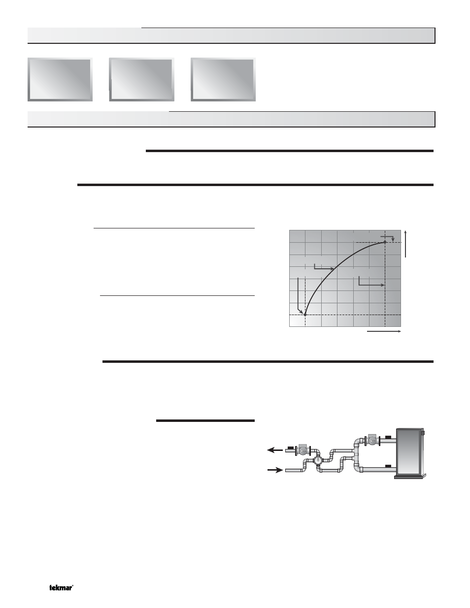
Outdoor Reset
When the outdoor design (OUTDR DSGN) setting is not set to OFF,
the 360 calculates a mixing supply water temperature based on the
outdoor air temperature. The 360 uses a Characterized Heating
Curve and optionally indoor temperature feedback from an indoor
sensor in this calculation.
Setpoint Control
When the outdoor design (OUTDR DSGN) setting is set to OFF, the
360 supplies a fixed mixing supply temperature equal to the MIX
TARGET setting. An outdoor sensor is not required during this mode
of operation.
FLOATING ACTION
A 24 V (ac) floating action actuator motor is connected directly to the 360 on the R Opn, R Cls, and C terminals (9,10 and 11). The
360 pulses the actuator motor open or close to maintain the correct mixed supply water temperature at the mix sensor when there
is a mixing demand. The mixing valve that the actuator is connected to can be either a 2-way, 3-way, or 4-way valve. A visual
indication as to whether the control is currently opening or closing the mixing valve is displayed in the LCD.
BOILER PROTECTION (BOIL MIN)
The 360 is capable of providing boiler protection from cold mixing
system return water temperatures. If the boiler sensor temperature
is cooler than the BOIL MIN setting while the boiler is firing, the 360
reduces the output to the mixing valve. This limits the amount of cool
return water to the boiler and allows the boiler temperature to recover.
This feature can only be used if a boiler sensor is installed.
Section A: General Operation
Mixing
Sensor
Boiler Supply
Sensor
OR
Boiler Return
Sensor
Decreasing Outdoor Temperature
Incr
easing W
a
te
r T
e
mperatur
e
Terminal Unit
Terminal Unit
Indoor Design
Indoor Design
Outdoor Design
Outdoor Design
Design Supply
Design Supply
Section A
General
Operation
Page 4 - 5
Section B
Mixing
Page 5 - 8
Section C
Boiler
Operation
Page 8 - 9