tekmar 360 Mixing Control User Manual
Data brochure, D 360, Mixing control 360
- Data Brochure
Mixing Control 360
D 360
03/09
1 of 20
© 2009
D 360 - 03/09
The Mixing Control 360 is designed to control the supply water temperature to a hydronic system in order to provide outdoor reset or
setpoint operation. The control uses a floating action mixing valve to regulate the supply water temperature, while protecting the boiler
against flue gas condensation. The control has a Liquid Crystal Display (LCD) to view system status and operating information.
Additional Functions Include:
• Quick Setup for easy installation and programming of control
• User comfort adjustment to increase or decrease building space
temperature
• Advanced settings to fine-tune building requirements
• Boiler Control for improved energy savings
• Powered mixing system pump output
• Optional indoor sensor for room air temperature control
• Test sequence to ensure proper component operation
• Setback input for energy savings
• 120 V (ac) power supply
• CSA C US certified (approved to applicable UL standards)
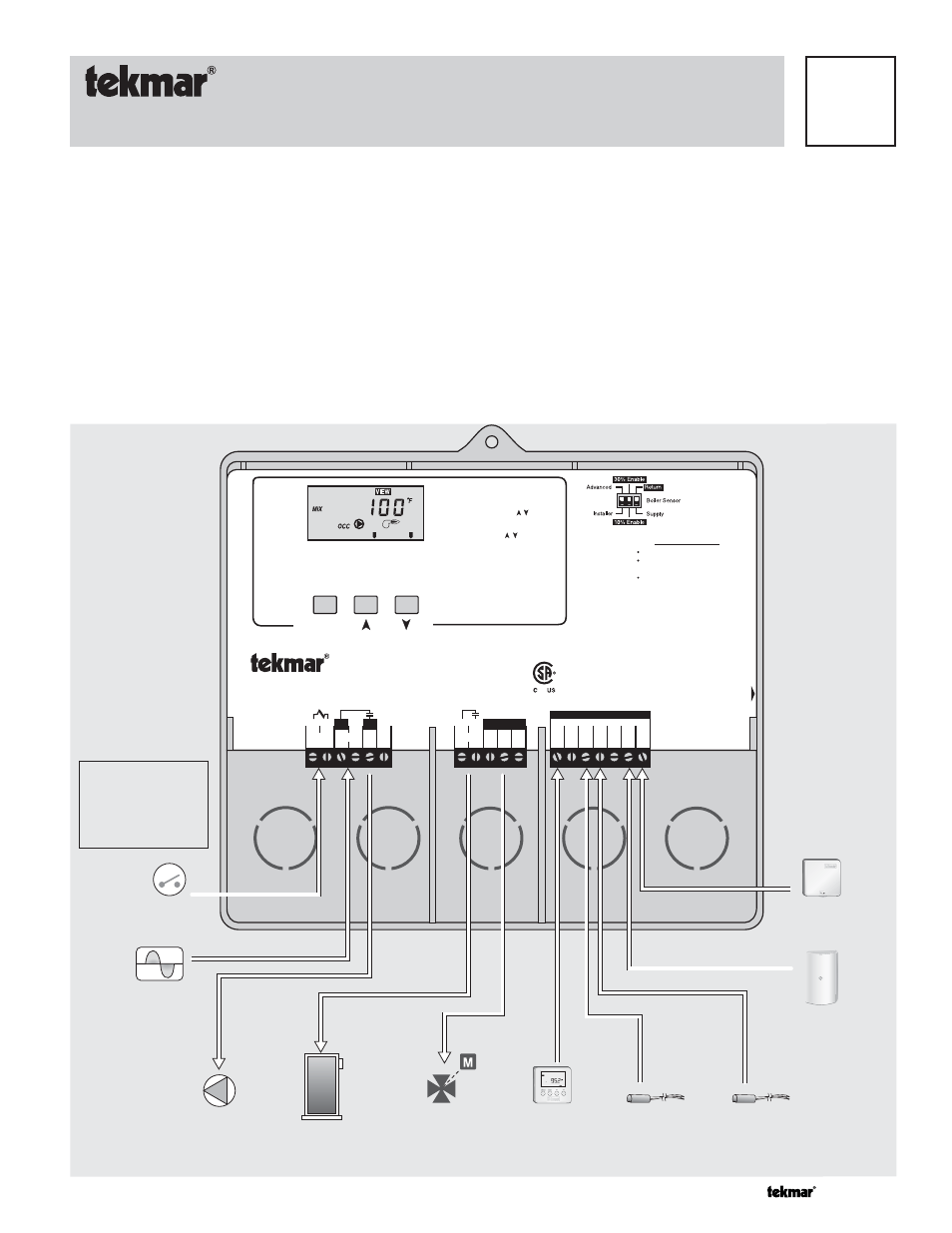
Output
Mixing Valve &
Actuating Motor
Input
Universal Sensor
Included
Input
Universal Sensor
Included
Input
tekmar Timer
Optional
Input
Outdoor Sensor
Included
Input
Indoor Sensor
Optional
Output
Boiler
Output
Mixing System
Pump
Input
120 V (ac) Power
Supply
Input
Mixing Demand
Signal
L
N
N
Opn Cls
Sw
Sys
Pmp
R
R
C
UnO Com Boil Mix Com Out Indr
1 2
3
5
9 10 11
4
6
7 8
12 13 14 15 16 17 18
Mixing Control 360
Floating Action
Do not apply power
Signal wiring must be
rated at least 300 V.
Mixing
Power
Boiler
Demand
Test
Terminal
Unit
Motor
Speed
Open Close Mixing
Demand
Made in Canada by
tekmar Control Systems Ltd.
tektra 912-02
Power:
120 V 50/60 Hz 1300 VA
Floating Output:
24 V (ac) 0.34 A 8 VA
Relays:
240 V (ac) 10 A 1/3 hp
Demand:
20 to 260 V (ac) 2 VA
H1
170E
Item
Powered Output
ROOM
-
Set to desired room temp.
OUTDR DSGN - Set to coldest (design)
outdoor temp.
Terminal Unit
Set to
High Mass Radiant -------
1
Low Mass Radiant -------
2
Fan Coil ------------------
3
Convector ----------------
4
Radiator ------------------
5
Baseboard ---------------
6
Refer to brochure for more information
Installer Instructions
To increase or decrease the
building temperature:
• Press the Item, , buttons
simultaneously for 1 sec. to
enter the ADJUST menu
• Use the, , buttons to
adjust the ROOM setting
Display defaults back to VIEW
menu after 20 sec.
Meets Class B:
Canadian ICES
FCC Part 15
Dat
e Code
Note:
Mixing demand must
be powered with 20 to
260 V (ac) before the
boiler is able to fire.