Photoflex SB-FLXFLSH400W FlexFlash 400W Strobe User Manual
Page 7
Visit photoflex
lightingschool
.com® for the best free learning resource!
For detailed specifications,
product tutorial videos
and more, please visit
www.photoflex.com®
PROFESSIONAL PHOTOGEAR
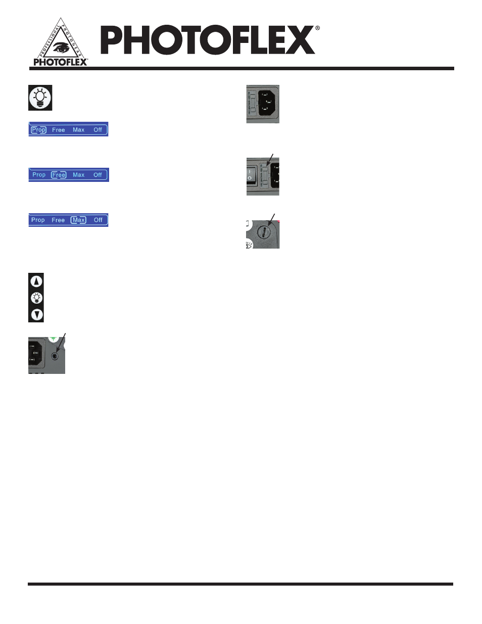
G. Modeling Light Function Button
This button will allow navigation through
the modeling light options such as:
Proportional
Sets the modeling light output to match the intensity
of the flash power setting.
Free
Allows independent adjustment of the modeling light
to use the unit as a continuous light and not a strobe.
Maximum
Sets the modeling light to its maximum power,
remaining at that level regardless of the power setting
for the strobe.
H. Modeling light power adjustment buttons
These two arrow buttons will adjust the
modeling power up or down when the
modeling lamp is set to
Free.
I. Sync Cord Input
The included sync cord (MiniPhone 1/8
inch / 3.5mm) plugs in here and the other
end (PC Connector) plugs into your
camera’s PC port. Wireless remote triggers
will also plug into this port using the same
miniphone plug to the wireless trigger.
Note: Some cameras do not include a PC plug for
use with sync cables, however adapters are
usually available for cameras that have a hot
shoe for an external flash.
J. AC Power Cord Input
A power cord is supplied for each
FlexFlash unit. Use only the cord
supplied. Do not remove the power cord
when the power is on as this can create a
hazardous situation.
K. Fuse Drawer
The fuse drawer is easily opened with a
flat-head (standard) screwdriver. Inside
you will see one fuse in use and an extra
fuse stored behind it.
L. Modeling Lamp Fuse Receptacle
The fuse holder is easily removed using a
flat-head (standard) screwdriver and
pushing in while giving a counter-
clockwise twist.
6