Tail wheel installation – E-flite P-51B Mustang 32e ARF User Manual
Page 8
8
E-flite P-51B Mustang 32e ARF Assembly Manual
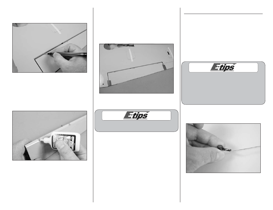
19. Inspect the hinges and mark on the flap where
the hinge point is in reference to the flap using a
felt-tipped pen.
20. Remove the flap from the wing. Make sure the
hinges are removed from the flap and wing at this
time. Apply a small amount of hinge glue in each of
the holes in the control surface for the hinges. Insert
the hinges so the hinge point aligns with the mark
made in the previous step. Allow the adhesive to
fully cure before proceeding.
21. Apply hinge glue in the holes for the hinges
in the trailing edge. Insert the flap hinges into the
trailing edge of the wing. Repeat Step 16 and 17
to check the position of the hinges. Wrap a small
amount of low-tack tape around the flap and inner
trailing edge, and around the flap and aileron to
keep it in position. Set the wing aside to allow the
adhesive to fully cure.
22. Repeat Steps 15 through 21 to attach the
remaining flap to the opposite wing panel.
Ensure your flaps can travel at least 1
1
/
2
-
inch (38mm) down for full defelection.
Tail Wheel Installation
Required Parts
Fuselage
Pre-bent tail wheel wire
2mm wheel collar 1-inch (25mm) tail wheel
Nylon steering arm 3mm x 4mm machine screw
3mm x 4mm setscrew
18-inch (457mm) pushrod wire, non-threaded
Required Tools and Adhesives
Hex wrench or ball driver: 1.5mm
Threadlock
Phillips screwdriver: #1
The following covers the installation of a fixed tail
wheel as supplied with your model. We have designed
the model so there is room to install a retractable
tail wheel if so desired. The installation will be up
to the modeler, as there are a variety of options
available. The radio tray also has an extra opening
to fit the servo necessary to operate this retract.
1. Connect the 18-inch (457mm) pushrod wire to
the nylon steering arm. Note the position of the arm
in relationship to the bend in the pushrod wire.