Machine safety switches, Si-ls42 series locking style switch, Electrical installation – Banner SI-QM100 Locking Style Switches User Manual
Page 6: Caution, Warning, Access to wiring chamber
Machine Safety Switches –
SI-LS42 Series Locking Style Switch
P/N 60099 rev. D
Banner Engineering Corp. • Minneapolis, MN U.S.A.
www.bannerengineering.com • Tel: 763.544.3164
Electrical Installation
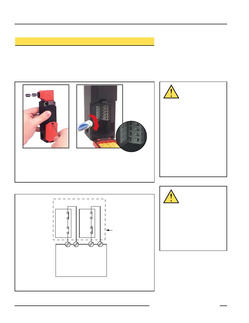
Access to Wiring Chamber
The wiring chamber is accessed via the hinged door. Simply insert a flat-blade
screwdriver, as shown in Figure 5, and pry gently down to open. Select the best wiring
entrance and thread in the ½" x 14 NPSM conduit adapter (supplied), or the optional M20
x 1.5 cable gland (page 12). The switch knockout will break loose with the final turn of
the conduit adapter or cable gland.
Figure . Access to wiring chamber – use a small flat-blade screwdriver
To connect wires to terminals:
1. Insert the screwdriver blade into the slot below the
desired wiring terminal.
2. Twist the screwdriver blade in the slot to open the
terminal jaws; insert wire.
3. Hold wire in place and remove screwdriver.
To open wiring chamber:
1. Insert the screwdriver
blade into slot in cover to
pry cover open.
Safety Switch #1
Safety Switch #2
Input
Channel
#1
Input
Channel
#2
2-channel Safety Module
(2-channel E-stop Module
2-channel Gate Monitor Module, etc.)
Single gate
or guard
Solenoid
Monitor
Contact
Solenoid
Monitor
Contact
Actuator
Safety
Contact
Actuator
Safety
Contact
Figure . Connect two redundant safety switches per interlock guard to an appropriate
2-channel input safety module.
NOTE: Refer to the installation instructions provided with the safety module for information
regarding the interface of the safety module to the machine stop control elements.
CAUTION . . .
Electrical Installation
Two safety switches
must be used for each interlock guard
to achieve control reliability or Safety
Category 4 (per ISO 1849-1, EN 94-1) of
a machine stop circuit. Use of only one
safety switch per interlock guard is not
recommended.
In addition, normally-closed safety contacts
from each of the two safety switches should
be connected to the two separate inputs of a
2-channel safety module or safety interface,
as illustrated in Figure 6. This is required to
provide monitoring for safety switch contact
failure, and to provide the necessary reset
routine, as required by IEC 60204-1 and
NFPA 79 machine safety standards.
WARNING . . .
Series
Connection of Safety
Interlock Switches
Monitoring multiple guards with a series
connection of multiple safety interlock
switches is not a Safety Category 4
Application (per ISO 1849-1, EN 94-1).
A single failure may be masked or
not detected at all. When such a
configuration is used, procedures must
be performed regularly to verify proper
operation of each switch.