Electrical installation, Access to the wiring chamber, Connection to the machine – Banner Compact Metal Style Safety Interlock Switches User Manual
Page 4
Banner Engineering Corp. • Minneapolis, MN U.S.A
www.bannerengineering.com • Tel: 763.544.3164
4
P/N 50159 Rev. F
Machine Safety Switch: SI-LM40 Series Limit Switch Style
Electrical Installation
Access to the Wiring Chamber
The wiring chamber is accessed via a cover plate. The metal switch body uses two
screws to hold the cover plate on. A conduit adapter is supplied to convert the M20 x
1.5 thread to ½"-14 NPT. An accessory cable gland which fits the M20 x 1.5 thread is
available (see page 7).
Connection to the Machine
Two contacts are offered. The contact between terminals 11 and 12 or 21 and 22 is the
safety contact, which is closed (i.e., it conducts) when the actuator is engaged. The
normally open contact located between terminals 23 and 24 is considered a monitoring
contact, which should not be used for safety switching.
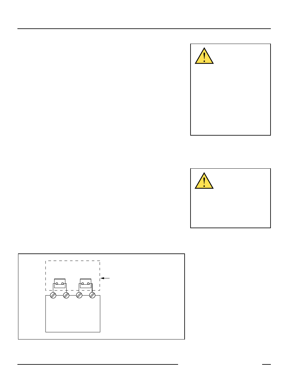
As illustrated in Figure 2, a normally closed safety contact (i.e., a safety contact that is
closed when the actuator is engaged) from each of two safety switches per interlock
guard must connect to a 2-channel safety module or safety interface in order to achieve
a control reliable interface to the master stop control elements of a machine. Examples of
appropriate safety modules include 2-channel emergency stop (E-stop) safety modules
and gate monitor safety modules.
Two functions of the safety module or safety interface are:
1. to provide a means of monitoring the contacts of both safety switches for
contact failure, and to prevent the machine from restarting if either switch fails;
and
2. to provide a reset routine after closing the guard and returning the safety switch
contacts to their closed position. This prevents the controlled machinery from
restarting by simply reinserting the safety switch actuators. This necessary
reset function is required by ANSI B11 and NFPA 79 machine safety standards.
Use only a positively driven, normally closed safety contact from each switch for
connection to the safety module. The normally open contact may be used for control
functions that are not safety-related. A typical use is to communicate with a process
controller. Refer to the installation instructions provided with the safety modules for more
information regarding the interface of the safety module to the machine stop control
elements.
CAUTION . . . Electrical
Installation
Two safety switches must be
used for each interlock guard to achieve control
reliability or Safety Category 4 (per ISO 13849-
1, EN 954-1) of a machine stop circuit. Use of
only one safety switch per interlock guard is not
recommended.
In addition, normally-closed safety contacts
from each of the two safety switches should be
connected to the two separate inputs of a 2-channel
safety module or safety interface, as illustrated in
Figure 6. This is required to provide monitoring for
safety switch contact failure, and to provide the
necessary reset routine, as required by IEC 60204-
1 and NFPA 79 machine safety standards.
WARNING . . . Series Connection
of Safety Interlock Switches
Monitoring multiple guards with
a series connection of multiple
safety interlock switches is not a Safety Category 4
Application (per ISO 13849-1, EN 954-1).
A single failure may be masked or not detected at
all. When such a configuration is used, procedures
must be performed regularly to verify proper
operation of each switch.
Figure 2. Connect two redundant safety switches per interlock guard to an appropriate
2-channel input safety module.
Safety
Switch
#1
Safety
Switch
#2
Input
Channel
#1
Input
Channel
#2
2-channel Safety Module
(2-channel E-stop Module
2-channel Gate Monitor Module, etc.)
Single gate
or guard
11 12
11 12
NOTE: Refer to the installation instructions
provided with the safety module for information
regarding the interface of the safety module to
the machine stop control elements.