Rotary dial positions – Banner SureCross DX80 Wireless Networks User Manual
Page 5
P/N 129232 rev. E
5
Banner Engineering Corp. • Minneapolis, MN U.S.A
www.bannerengineering.com • Tel: 763.544.3164
SureCross™ DX80K Wireless Configured
FlexPower™ Kit
Do not change the position of the right rotary dial on the Node(s) in this kit. The factory configured this kit and assigned a device ID to the
Node(s) based on the kit configuration requirements. If you change the Node’s right rotary dial, your kit will not work.
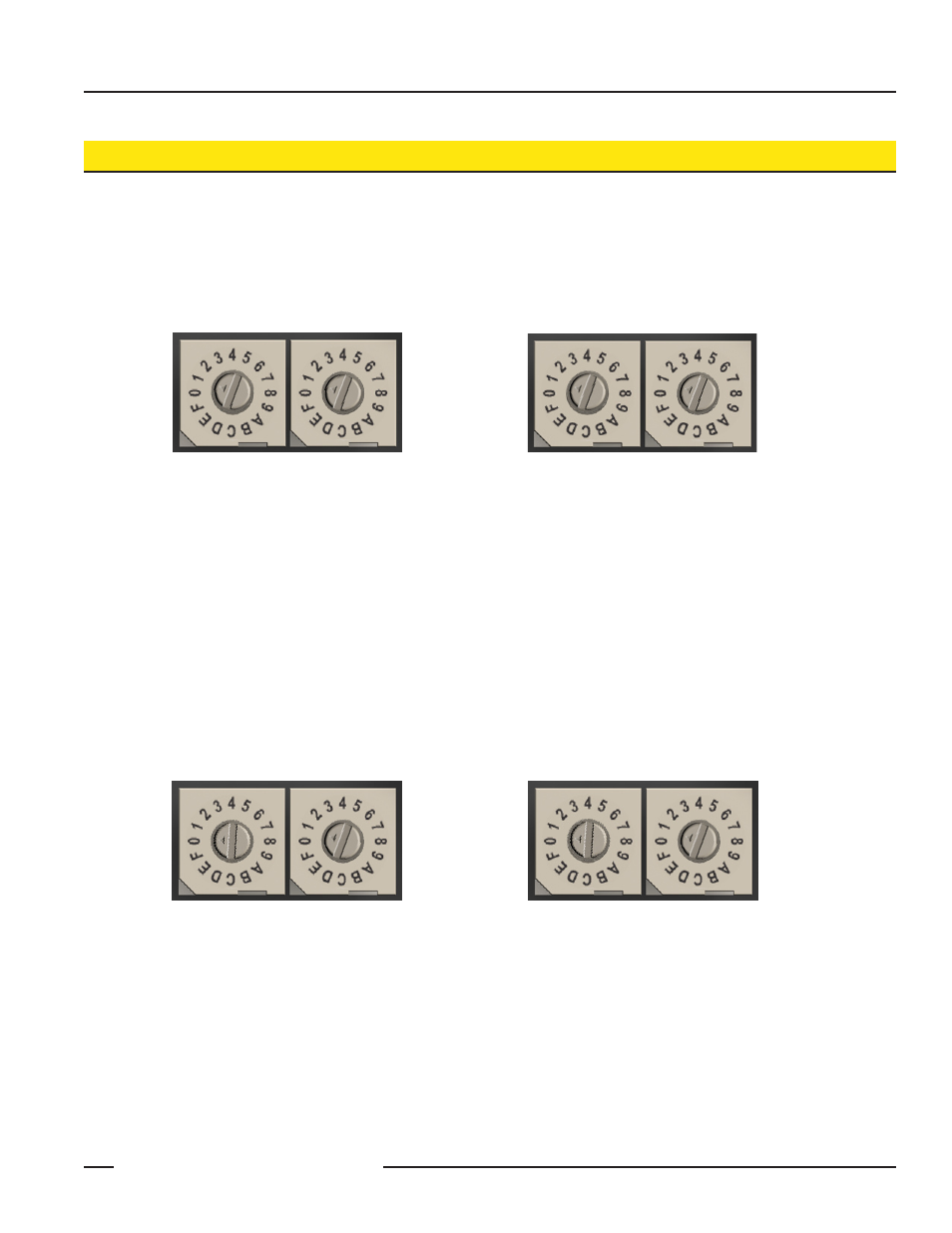
Rotary Dial Positions
Rotary Dial Addressing Mode
When using Rotary Dial Addressing Mode, the Gateway’s and Node’s rotary dials are in the correct position. The left rotary dial establishes the
Network ID and the right dials establish the Device ID.
When using multiple networks within range of each other, set each network to a different Network ID using the left rotary dial. DO NOT change
the position of the right rotary dials or your network and its preconfigured mapping will not work.
Gateway rotary dial positions, from the
factory.
Node rotary dial positions, from the
factory.
Extended Addressing and Binding Mode
When using binding to establish your networks, the rotary dial positions on the Gateway indicate which Node’s I/O values are displayed on the
Gateway’s LCD. Adjust the left rotary dial to zero and the right rotary dial to one.
For the Nodes, set the left rotary dial position to zero, and DO NOT change the position of the right rotary dial or your network and its
preconfigured mapping will not work.
Gateway rotary dial positions.
Node 1’s rotary dial positions.