Flex power™ device configuration – Banner SureCross DX80 Wireless Networks User Manual
Page 3
P/N 129232 rev. E
3
Banner Engineering Corp. • Minneapolis, MN U.S.A
www.bannerengineering.com • Tel: 763.544.3164
SureCross™ DX80K Wireless Configured
FlexPower™ Kit
FlexPower™ Device Configuration
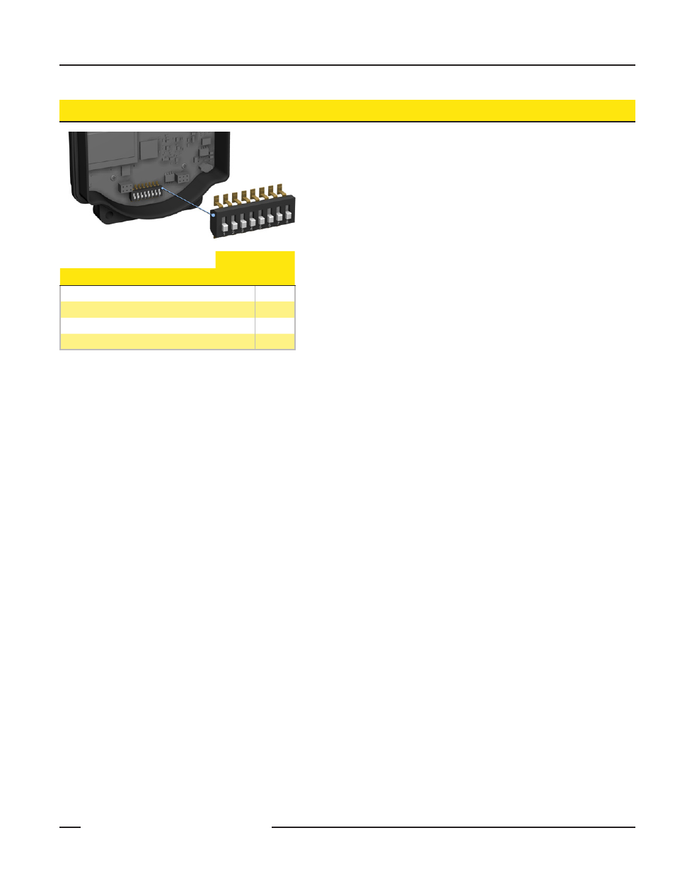
Switches
Device Settings
1
2
Rotary Switch Address Mode
OFF*
Extended Address Mode
ON
Analog Configuration
OFF*
Discrete Configuration
ON
* Default configuration
Do not change the position of any DIP switch other than DIP switches
1 and 2. This kit is configured at the factory.
Cycle Power
After making any changes to the DIP switch positions, cycle power
to the device to activate the changes. For devices with batteries
integrated into the housing, remove the battery for one minute to
cycle power to the device.
Accessing the DIP Switches
To access the DIP switches, follow these steps:
Unscrew the four screws that mount the cover to the bottom
1.
housing.
Remove the cover from the housing without damaging the
2.
ribbon cable or the pins the cable plugs into.
Gently unplug the ribbon cable from the board mounted into
3.
the bottom housing.
Remove the black cover plate from the bottom of the
4.
device’s cover.
The DIP switches are located behind the rotary dials. After making the
necessary changes to the DIP switches, place the black cover plate
back into position and gently push into place. Plug the ribbon cable
in after verifying that the blocked hole lines up with the missing pin.
Mount the cover back onto the housing.
Address Mode
The SureCross wireless devices may use one of two types of
addressing modes: rotary switch addressing or extended addressing.
In rotary switch address mode, the left rotary dial establishes the
network ID and the right rotary dial sets the device ID. The wireless
network is restricted to a maximum of 16 devices.
Extended address mode binds Nodes to a specific Gateway, allowing
network expansion to more than 16 devices in a wireless network.
For more information on extended address mode, refer to the
SureCross™ Wireless I/O Network product manual.
The device ships in rotary switch address mode by default, with the
DIP switch in the OFF position. To use extended address mode,
change the DIP switch to the ON position.
Discrete Input Type
Select the discrete input type, sourcing (PNP) or sinking (PNP), using
this DIP switch.
Boost Voltage
Select the boost voltage setting for the continuous power supplied to
the sensor powered by this FlexPower Node.
Warm-Up Time
The warm-up time defines how long the device must power up the
sensor before a stable sensor reading is taken.
Sample and Report Rates
The sample rate defines how often the Node samples the sensor. The
report rate defines how often the Node communicates the I/O status
to the Gateway. For FlexPower™ applications, setting the sample
and/or report rates to slower rates extends the battery life.
Change of state reporting sets the system to report only when the
value crosses the threshold setting.
Analog or Discrete Configuration
Select between an analog configuration or a discrete configuration
using the DIP switch specified in the table. The default switch settings
for this device are all in the OFF position.
Host Configured
Selecting “Host Configured (override switches)” uses the factory’s
default configuration for this device or allows a host system to set
parameters. If the host configured option is not selected, use the DIP
switches to configure the device parameters.