Installation instructions – Brandmotion FDMC-1220 User Manual
Page 4
INSTALLATION INSTRUCTIONS
1220 Instructions 6-26-14.docx
Page 4 of 5
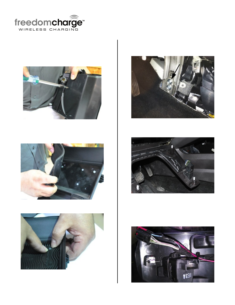
Step 13: Route black connector of Charging
Module through 1/2" hole and place module
in bin. Flip tray over and insert the (4) 3/8”
Pan Head T-15 Torx Screws through tray into
module.
Step 14: Install Non-Slip Freedom Charge
Mat to Wireless Charging Module. Place the 4
locator pins in corresponding holes.
Step 15: Firmly press Mat around LED.
Step 16: Attach Ground Eyelet of Power
harness to upper 13mm Bolt on drivers foot
well metal console bracket.
Step 17: Pull down driver side knee bolster
trim to reveal interior air sensor plug.
Step 18: Splice Red wire of Power Harness to
the Blue (12v ignition) wire of the interior
sensor plug.
RECOMMENDED: Solder wires and cover with Heat
Shrink Tubing
- 1008-9527-V1 (18 pages)
- 1008-9527-V2 (38 pages)
- 9002-1010 (8 pages)
- 9002-9503-V1 (2 pages)
- 9002-9503-V2 (12 pages)
- 1008-9520-V1 (2 pages)
- 1008-9520-V2 (34 pages)
- 9002-8836 (7 pages)
- 1013-9530-V1 (2 pages)
- 1013-9530-V2 (16 pages)
- 1009-9518 (7 pages)
- 1009-9517 (18 pages)
- 9002-1015 (6 pages)
- 9002-8522 (6 pages)
- 9002-8525 (5 pages)
- 9002-8523 (7 pages)
- 9002-8524 (5 pages)
- 9002-8521 (5 pages)
- 9002-8520 (4 pages)
- 9002-9651 (2 pages)
- 9002-9650 (2 pages)
- 9002-9511 (4 pages)
- 9002-9516 (3 pages)
- 9002-6014 (1 page)
- 9002-9510-V1 (3 pages)
- 9002-9510-V2 (3 pages)
- 9002-9618 (2 pages)
- 9002-9515 Installation Instructions (2 pages)
- 9002-9515 Wiring Instructions (2 pages)
- 9002-9608 (2 pages)
- 9002-9613 (2 pages)
- 1110-2519 (2 pages)
- 9002-9702 (1 page)
- 9002-9703 (2 pages)
- 1110-2518 (2 pages)
- 9002-9704 (1 page)
- 9002-9701 (1 page)
- FLTW-7604 (2 pages)
- 9002-7607 (2 pages)
- 9002-7609 (2 pages)
- 9002-7608 (2 pages)
- 9002-7605 (3 pages)
- 9002-7606 (2 pages)
- FLTW-7603 (3 pages)
- 9002-8501 (4 pages)