Installation instructions, Pinout reference chart, Chassis harness connection chart – Brandmotion 9002-8536 User Manual
Page 3
INSTALLATION INSTRUCTIONS
8536 Instructions 5-28-14.docx
Page 3 of 4
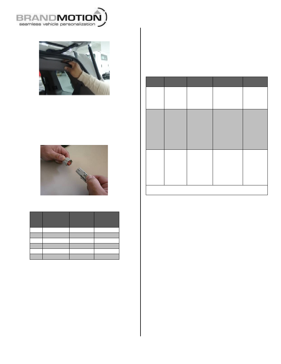
Step 12: Route Camera Harness towards the side
of the vehicle that supplies power.
Step 13: Connect Camera Harness to supplied
Chassis Harness. The optimal location for this
junction may occur at the top of the liftgate or the
inner edge of the trunk. (Note: Most vehicles have
existing wires passing through this area; use this
route if at all possible).
Pinout Reference Chart
PIN
#
FUNCTION
CAMERA
HARNESS
COLOR
CHASSIS
HARNESS
COLOR
1
Video (+)
Yellow
White
2
Shield
White
Blue
3
Reverse
Blue
Green
4
Video (-‐)
Brown
Brown
5
Ground
Black
Black
6
Ignition
Red
Red
Step 14: Route Chassis Harness forward. It may
be necessary to remove sill plates, pillar covers,
seat bases, side panels, etc. using a Plastic Trim
Removal Tool. In some cases, seatbelt bolts must
be removed. (CAUTION: Any bolts removed for
safety devices must be retightened to
manufacturer’s torque specifications).
Step 15: Determine location of vehicle Ignition
power and Ground. Using a multi-meter or
computer-safe test light, locate which side of the
vehicle contains the wires into which you will
connect Chassis Harness wiring (see chart below).
Chassis Harness Connection Chart
Wire
Color
Polarity
Function
Description
Location
note
Red
12v +
Ignition
controlled
power
This lead
displays 12 volt
+ when the
key is in the
RUN position
Commonly
found on
main
Ignition
harness.
Black
(–)
Ground
Chassis ground
A ground
bolt is
commonly
found in
the front
kick panel
area with
other wires
attached.
Green
12v +
Reverse
trigger
This lead is
activated when
the vehicle is
engaged into
Reverse
Commonly
found in
front kick
panel area
on harness
coming
from rear of
vehicle.*
*If Reverse cannot be located, connect the both the Red and Green
wires to Ignition power.
Step 16: Secure Camera Harness to existing
vehicle wiring. This will minimize chance of binding
or otherwise damaging the harness.
RECOMMENDED: Wire Ties or Electrical Tape.
Step 17: Splice the red and green Chassis Harness
leads into the corresponding vehicle wires and the
black wire to chassis ground. (Note: Soldering
recommended or T-taps as optional connection
method). RECOMMENDED: Attach an eyelet to
the black ground wire.
Step 18: Use a Plastic Trim Removal Tool, 7 or
10mm Socket, and/ or Phillips Screwdriver to
remove garnish and fasteners securing the radio
display.