Installation instructions – Brandmotion 9002-8531 User Manual
Page 3
INSTALLATION INSTRUCTIONS
8531 Instructions 9-5-14.docx
Page 3 of 4
Step 11: Align the Camera Harness head so the
key lines up with the slot in the camera, and plug
in the connector. Snug the supplied screws with a
Phillips Screwdriver to create a watertight seal but
do not over tighten.
Step 12: Mount Camera using supplied
hardware. Insert the supplied rubber Well Nuts
into the two outer Camera Mount holes and use a
Phillips Screwdriver to thread the supplied Bolts in
but do not tighten them down just yet.
Step 13: Connect Camera Harness to gray
connector end of supplied Chassis Harness.
Step 14: Secure Camera Harness to factory wiring
using supplied Wire Tires.
Step 15: Route Camera and/ or Chassis Harness
along existing wiring and secure using supplied
Wire Ties. IMPORTANT: Ensure harnesses move
freely with the trunk or liftgate.
Step 16: Route Chassis Harness forward. It
may be necessary to remove sill plates, pillar
covers, seat bottoms, side panels, etc. Use a plastic
trim removal tool to avoid damage to trim pieces.
In some cases, seatbelt bolts at the bottom of the
pillars must be removed. (CAUTION: Any bolts
removed for safety devices must be retightened to
manufacturer’s specified torque specifications.)
Step 17: Route supplied Chassis Harness to
center dash/console area.
CAUTION: Keep harness away from accelerator, brake
pedal, and parking brake assembly.
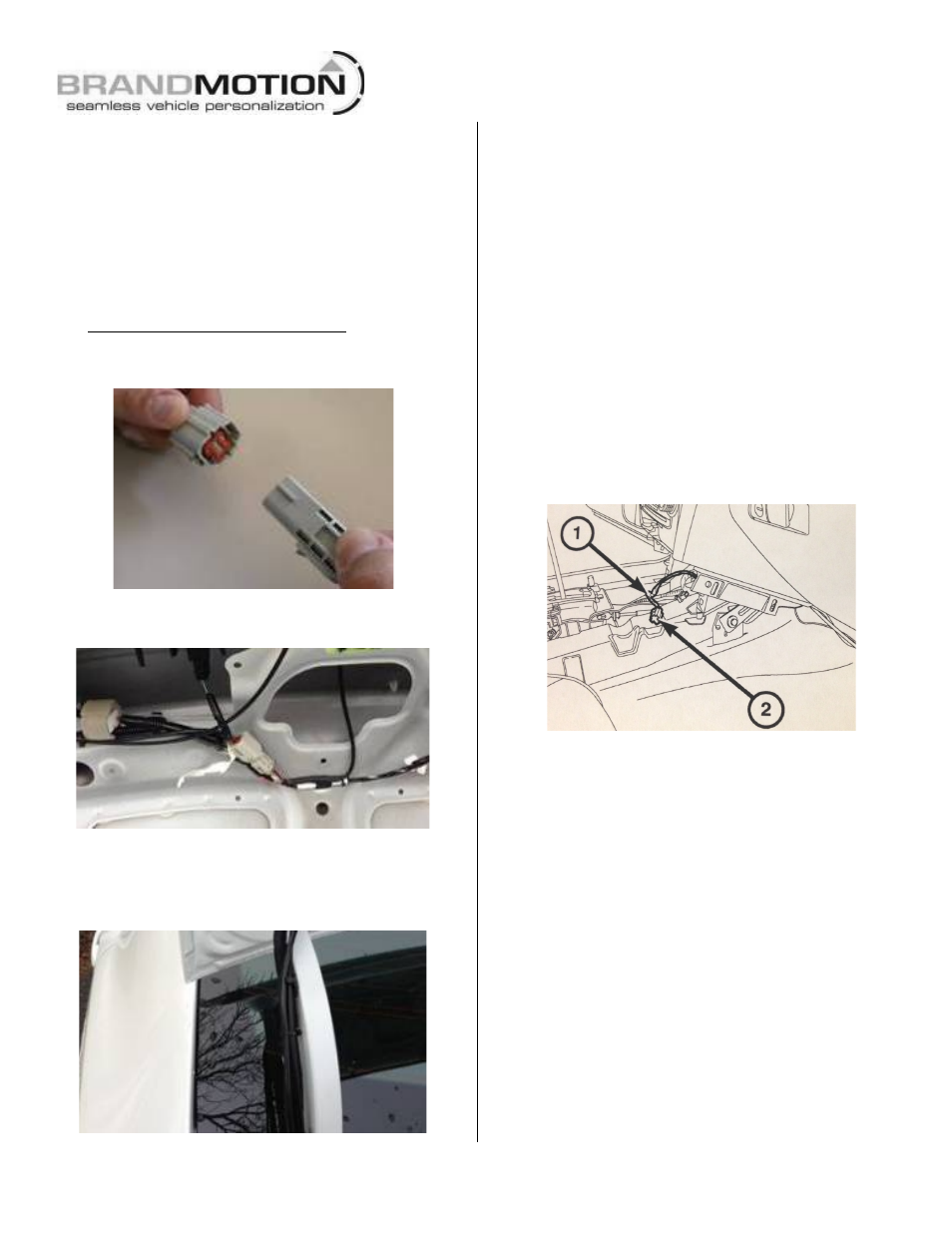
Step 18: Use a Plastic Trim Removal Tool to
remove console components to access wire harness
supplying the 12v accessory outlet (2). Unwrap
just enough of the insulating tape (1) from the
wires to make splices for the Chassis Harness
connections.
Step 19: Splice both the Red and Green wires of
supplied Chassis Harness to the Dark Blue/Pink
wire. Next, splice Black wire of supplied Chassis
Harness to the Black Ground wire. Note: Solder &
cover with Heat Shrink Tubing (recommended) or
T-taps as an optional connection method.
WARNING: Disable airbag system before attempting any
steering wheel, steering column, or instrument panel
component diagnosis or service. Disconnect and isolate
negative battery (ground) cable, then wait two minutes for
the airbag system capacitor to discharge before performing
further diagnosis or service. Failure to take the proper
precautions may result in accidental airbag deployment and
possible serious or fatal injury.
Step 20: Use a Plastic Trim Removal Tool to
remove dash trim and radio bezel to expose the (4)
screws securing the radio head unit and remove
them using a 7mm socket.
Step 21: Unplug all radio connectors from the
radio head unit and set radio aside.