Installation instructions, Pinout reference chart – Brandmotion 9002-8525 User Manual
Page 4
INSTALLATION INSTRUCTIONS
INSTALLATION INSTRUCTIONS
8525 Instructions 7-18-13.doc
Page 4 of 5
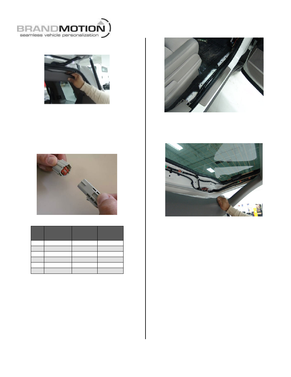
Step 13: Route Camera Harness towards the
side of the vehicle that supplies power.
Step 14: Connect Camera Harness to
supplied Chassis Harness. The optimal location
for this junction may occur at the top of the liftgate
or the inner edge of the trunk depending on vehicle
in which installation is in (Note: Most vehicles may
already have existing wires passing through this
area; use this route if at all possible).
Pinout Reference Chart
PIN
#
FUNCTION
CAMERA
HARNESS
COLOR
CHASSIS
HARNESS
COLOR
1
Video (+)
Yellow
White
2
Shield
White
Blue
3
Reverse
Brown
Green
4
Video (-)
Gray
Brown
5
Ground
Black
Black
6
Ignition
Red
Red
Step 15: Route Chassis Harness forward. It
may be necessary to remove sill plates, pillar
covers, seat bottoms, side panels, etc. In some
cases even the seatbelt bolts at the bottom of the
pillars must be removed.
CAUTION: Any bolts removed for safety devices
must be retightened to manufacturer’s specified
torque specifications). Use a Plastic Trim
Removal Tool to avoid damage to trim pieces.
Step 16: Secure Camera Harness to existing
vehicle wiring using supplied Wire Ties. This
will minimize chance of binding or otherwise
damaging the harness
Step 17: Remove vehicle mirror by twisting it
approximately 30 degrees.
Step 18: Carefully twist on the supplied Mirror
approximately 30 degrees until it clicks into place.
Step 19: Route Mirror wiring. Tuck the harness
beneath the vehicle headliner and down the A-pillar
toward the Chassis Harness which you installed
previously.