Installation instructions – Brandmotion 9002-8525 User Manual
Page 3
INSTALLATION INSTRUCTIONS
INSTALLATION INSTRUCTIONS
8525 Instructions 7-18-13.doc
Page 3 of 5
Step 8: Preload the (2) Screws into the Camera
Harness connector.
Step 9: Align Camera Harness head so the key
lines up with the slot in the camera, and plug in
connector. Snug supplied Screws with a Phillips
Screwdriver to seal but do not over tighten.
Step 10: Mount the Camera using the supplied
hardware. Insert the (2) supplied Rubber Well Nuts
into the outer 5/16” camera mount holes.
Step 11: Thread the (2) supplied Bolts through the
Camera Mount and into the Well Nuts using a
Phillips Screwdriver but do not tighten the Bolts all
the way down just yet.
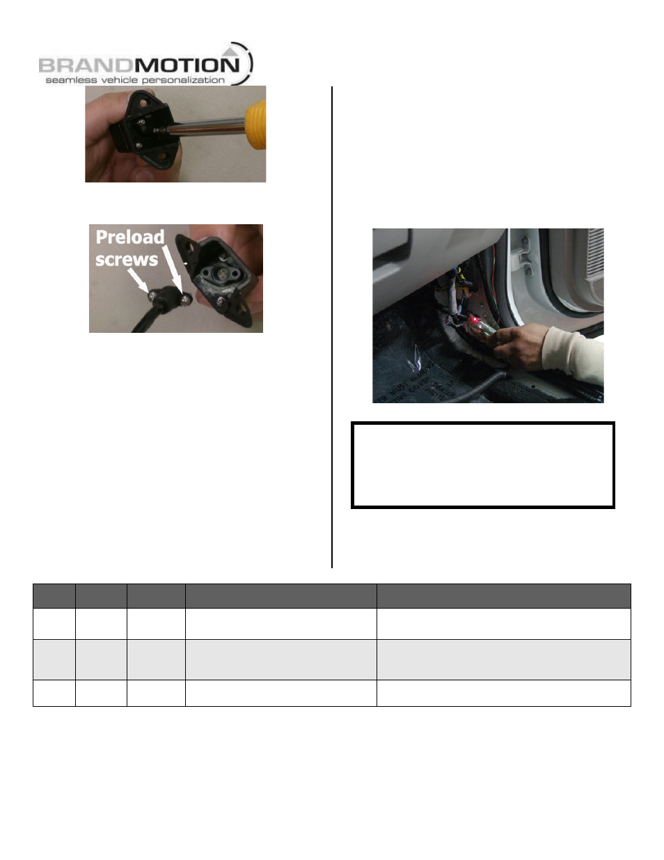
Step 12: Determine location of vehicle power
and ground. Using a vehicle specific service guide
and/or vehicle specific wiring diagram and a multi-
meter or computer-safe test light, locate which side
of the vehicle containing the following wires into
which you will need to tap for the Mirror Harness
wiring (see Chart A).
Note: Brandmotion provides Red, Green, and
Black wires at both ends of the supplied
Mirror Harness because it is sometimes
possible to tap into the existing mirror harness
for Ignition (12v +), Reverse signal (+), and
Ground.
Chart A
Wire
Color
Polarity
Function Description
Location note
Red
12v +
Ignition
power
This lead displays 12 volt + when the
key is in the RUN position
Commonly found on the main Ignition harness.
Black
(–)
Ground
Chassis ground
A ground bolt is commonly found in the front kick
panel area with other wires attached. In some
cases you may need to supply a new screw.
Green
12v +
Reverse
trigger
This lead is activated when vehicle is
engaged into reverse gear
Commonly found on the front kick panel area on
the harness coming from the rear of the vehicle
CAUTION:
Once correct wires have been identified,
turn Ignition key OFF and DO NOT TURN key
back ON until the install has been completed
(Step 22).