Brandmotion 9002-8522 User Manual
Page 4
!"#$%&&%$!'"(!"#$)*+$!'"#
8522 Instructions 7-10-13.doc
Page 4 of 6
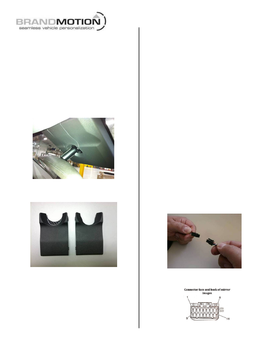
Step 17: Remove vehicle mirror. Unplug the
16-pin connector from the rear of the vehicle’s
mirror, use a T20 Torx bit to loosen the screw
securing the mirror, and slide the mirror off the
windshield mounting tab.
CAUTION: Removing the mirror can cause
damage to the windshield.
NOTE: Some vehicles have Mirror Mounting
Covers (the 2012 Equinox is shown below).
Refer to our application guide for affected
vehicles. If equipped, remove the cover with a
plastic trim tool. If the vehicle has a center
portion, remove it.
Next, using a Roto Tool remove the striped
area of the center cover as shown below.
The reworked cover is on the right.
Step 18: Attach supplied Mirror to the
windshield using a T20 Torx Driver. This
mirror has a Wedge/ D-tab style mounting base.
Please check our compatibility chart to make sure it
is compatible with your vehicle (adapters are
available for specific applications separately).
CAUTION: Torque for the mirror screw that
attaches to the windshield tab is 1.8 Nm (16
lb-in) and cannot exceed 2.2 Nm (19.5 lb-in).
Step 19: Plug the 16-pin connector of the supplied
Mirror Harness into the supplied Mirror.
Step 20: Route the 6-pin connector end of the
Mirror Harness along with the green, red, and black
wires under the headliner.
Step 21: Route the Mirror Harness down the inside
of the A-pillar trim closest to the ignition and
reverse locations for the vehicle.
Step 22 (if required): Wiring the Mirror
Harness.
NOTE: It may not be necessary for you to use the
Green and Red supplied wires below; most GM
vehicles already have these locations populated. If
wires already exist in these locations, test the leads
using a multimeter for the correct signal).
If the wires do not exist, splice the red and green
wire leads to the wires listed for the vehicle on
Page 6. (Soldering recommended or T-taps as
optional connection method):
Red - Ignition controlled power 12v+ when key is
turned ON and 14.4v or better when vehicle is
running.
Green - Connect to Reverse + power (backup lamp).
Step 23: Attach eyelet of black chassis ground
wire of the supplied Mirror Harness to an existing
body bolt.
Step 24: Connect the 6-pin connector of the
supplied Mirror Harness to the supplied Chassis
Harness.
Tuck any excess harness beneath the headliner
taking care not to bind the wires.
White dot
identifies
cavity 1