Figure 6 controls and indicators, Adjust set-points – Bird Technologies 3171B020 User Manual
Page 23
11
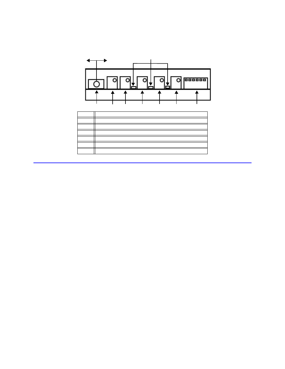
Figure 6 Controls and Indicators
Adjust Set-Points
1.
Set the CALIBRATE/OPERATE switch to the CALIBRATE position (to the left).
2.
Do one or more of the following:
•
Set the Forward Power Level Alarm Trip Point
a.
Adjust the forward reference potentiometer to set the meter to indicate the
power level at which the forward alarm is to be tripped.
b.
Adjust the forward set-point potentiometer until the miniature LED to the left
of the potentiometer is just at the transition from off to on.
Note: Turning the potentiometer clockwise will raise the set-point and turn the
light off.
•
Set the Reflected Power Level Alarm Trip Point
a.
Set the reflected trip point, on the reflected potentiometers, in a similar
manner to the forward trip point. See “Set the Forward Power Level Alarm
Trip Point” on page 11.
Note: The alarm will trip during this operation. It can be reset when com-
pleted.
•
Set the Confirm Set-Point
a.
Adjust the forward reference potentiometer to set the trip point level.
b.
Adjust the confirm set-point potentiometer until the miniature LED to the left of
the potentiometer is just at the transition from off to on.
Note: If the confirm output is not used, it is not necessary to adjust the confirm
set-point potentiometer.
3.
Return the CALIBRATE/OPERATE switch to the OPERATE position (to the right).
1
Calibrate/Operate Switch
2
Forward Reference Adjustment Potentiometer
3
Reflected Reference Adjustment Potentiometer
4
Forward Set Point Potentiometer
5
Reflected Set Point Potentiometer
6
Confirm Set Point Potentiometer
7
Forward Monitor Active Delay Dip Switch
1
2
3
4
5
6
7
LED’s
Calibrate
Operate
Switch