Models 3171b and 3171b020, Initial setup, Preparation – Bird Technologies 3171B020 User Manual
Page 22: Checking the led light, Removing the faceplate, Figure 5 face plate removal, Checking the led light removing the faceplate
10
Models 3171B and 3171B020
1.
Insert the line section in the coaxial RF coaxial transmission line.
2.
Connect the DC cable to the line section.
3.
Run the DC cable to the rack console unit.
Note: If the back of the unit is not accessible from the rear of the rack mount,
all connections to the unit must be made before the panel is secured in place.
4.
Ensure that the 115/230 line voltage switch is in the correct position for the voltage
supplied.
Note: 3170B series Wattcher is shipped with a fuse and fuse drawer set for
115V operations. For 230V operations, see “Changing Fuse Drawer for 230V
Operation” on page 19..
5.
Connect the AC power cord from the Wattcher unit to an appropriate source.
Note: Make DC power connections if needed.
6.
Secure the panel to the rack mount using appropriate fasteners.
Initial Setup
Preparation
Checking the LED Light
When either AC or DC power is applied to the unit, the yellow reflected monitor active LED should light. If this light
does not come on, disconnect the power cord and refer to Chapter 5, Maintenance. With the yellow reflected mon-
itor active LED lit, signifying power is ON and the unit is operational, proceed with the initial setup be low.
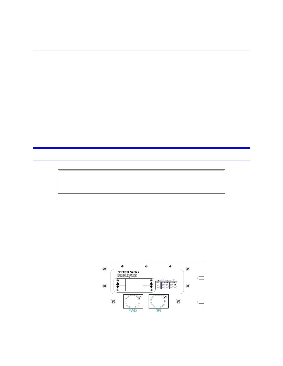
Removing the Faceplate
1.
Remove the four screws found in the corners of the faceplate.
Note: This exposes the circuit board on which the calibration controls are
located.
2.
Set the CALIBRATE/OPERATE switch to the calibrate position (to the left).
Figure 5 Face Plate Removal
WARNING
Do not use electrically conductive tools for calibration when the front panel is
removed.
Damage to the unit and or the possibility of electrical shock exists.
Remove
these
screws