Wiring the drives signal for a compact, Connecting a fault relay – Rockwell Automation 4100 REC Resolver to Encoder Converter Installation and Setup Manual User Manual
Page 27
Publication 999-126 - February 1996
22
Installation & Hook-Up
Wiring the Drives Signal for a
Compact
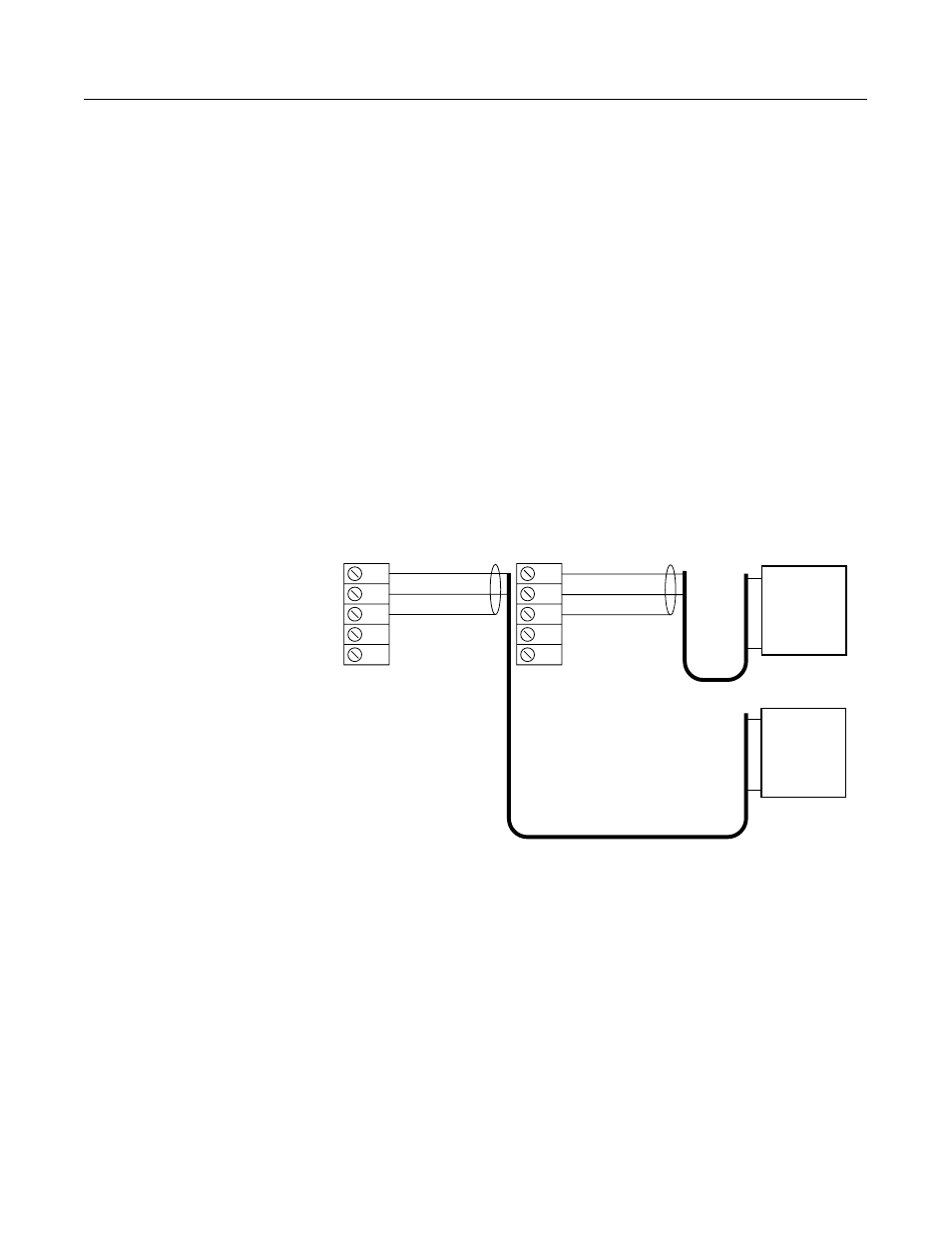
When using the REC with an S Class Compact, the drive reference
signals (+/-10V) are passed from the Compact to the REC at
terminals 8, 9, and 10 on plug A (Axis 1), and at terminals 3, 4, and 5
on Plug B (Axis 0). To wire the drives signal:
1. Connect the drive signal to the servo amplifier using a twisted,
shielded cable (Belden 9501 or equivalent).
2. Wire the cable leads to the appropriate Power & Drives plugs ofr
the required axis. Figure 2.12 shows where to connect the drives
reference signals to the Power & Drives connector.
Both Axis 0 and Axis 1 can have drive signals present at their
connectors.
Note:
You do not need to wire the drive reference signal to the 1394
because it handles the reference signal output internally.
Figure 2.12
Wiring the Drive Reference Signal to an S Class Compact Motion Controller
Important: Anchor the cable so that no more than 2 feet of cable is
left unsupported. The excessive weight of an unanchored
cable could pull the plug out of the connector.
Connecting a Fault Relay
The REC is equipped with a fault detector that handles internal logic
voltage malfunctions and resolver phase loss faults. The fault detector
consists of:
•
An internal relay contact output that opens for each axis
•
An LED indicator that turns red for each axis
•
An encoder driver disabler for each axis
10
9
8
7
6
5
4
3
2
1
Ref +
Ref -
Servo
Amplifier
Axis 0
Ref +
Ref -
Servo
Amplifier
Axis 1
1 Reference +
1 Reference -
1 Reference Shield
0 Reference +
0 Reference -
0 Reference Shield
Plug A
Plug B