Rockwell Automation 1797-IE8NF FLEX Ex 8 Input Analog, HART and Noise Filter Module User Manual
Page 14
14 FLEX Ex 8 Input Analog, HART, and Noise Filter Analog Modules
Publication
1797-5.5 - September 2011
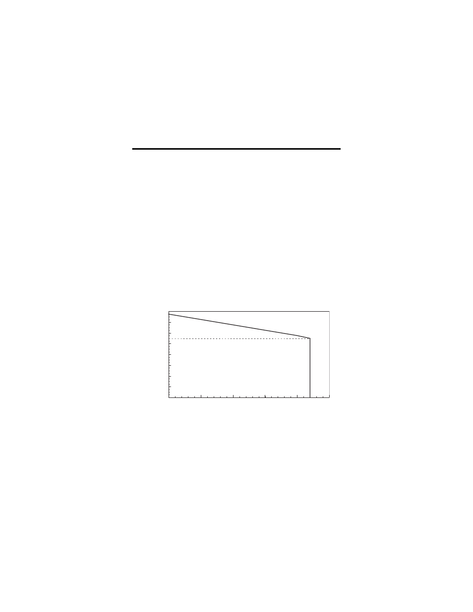
1797-IE8 and 1797-IE8NF Field Transmitter Supply Characteristic
The field transmitter supply can be modeled as a 21.5V source with a 273
Ω
series resistance. (See the following graph.) This provides a simple and useful
mechanism to determine transmitter and loop compatibility.
The actual transmitter supply contains three ranges of impedance with the
following characteristics:
•
The output voltage is
≈
21.5V for load currents of 0 mA.
•
If the load is more than
≈
680
Ω
but less than
∞Ω
, the transmitter
supply is in a constant resistance region (
≈
273
Ω
).
•
For load impedance between 0 and
≈
680
Ω
, the transmitter supply
current is in constant current mode (
≈
22 mA).
If an intrinsic safety fault occurs in the field transmitter supply of any channel,
every channel’s field transmitter power is shutdown.
The following graph depicts the typical transmitter load characteristic.
The normal module field side power consumption is 7.5 W when all channel
21.5V sources (+) are loaded. If field devices are used that are powered
separately, the module field-side power consumption can be determined by
Field_Side_Power = 9.5V x (300 mA + n x 55 mA). Where n is the number of
field devices that are supplied by the 1797-IE8 or 1797-IE8NF.
Voltage
mA
16
14
12
10
8
6
4
0
5
10
15
20
25
43002
2
0
18
20
22
V DC