Rockwell Automation 57C422B 2 Axis Servo Module User Manual
Page 82
4-54
2-Axis Servo Module M/N 57C422B
cam will never be started. The value is in counts.
4.50.3 Register 128: Number of Points in Cam Table
Register 128 is used to select the number of points in the
cam table that are filled-in. This number represents bytes or
words for a time cam profile or double precision integers for a
position cam table. This register is read by the module
whenever the "do cam profile" bit is set in register 66.
Attempts to modify register 128 while the axis is moving will
be ignored by the module. See figure 4.55.
4.50.4 Register 129: Time Between Points in Cam
Table
Register 129 defines the time between points in the cam
table. The unit is scans. The time can be calculated with the
following equation:
Time =
cam cycle time
number of profile points in the cam table * .00125
The time must be greater than or equal to 1. See figure 4.55.
4.50.5 Register 130: Cam Mode
Register 130 is used to select setup information about both
time and position type cams and to enable the position cam.
If position cam is selected, only bits 3 and 7 are used. See
figure 4.55.
The data format bit defines the data in the cam profile table
as either bytes or words.
If the table direction bit is set to forward, the cam moves from
the lowest register (132) to the highest defined register
(<=2046) in sequence. If it is set to reverse, the cam will
move from the highest defined register ( <=2046) to the
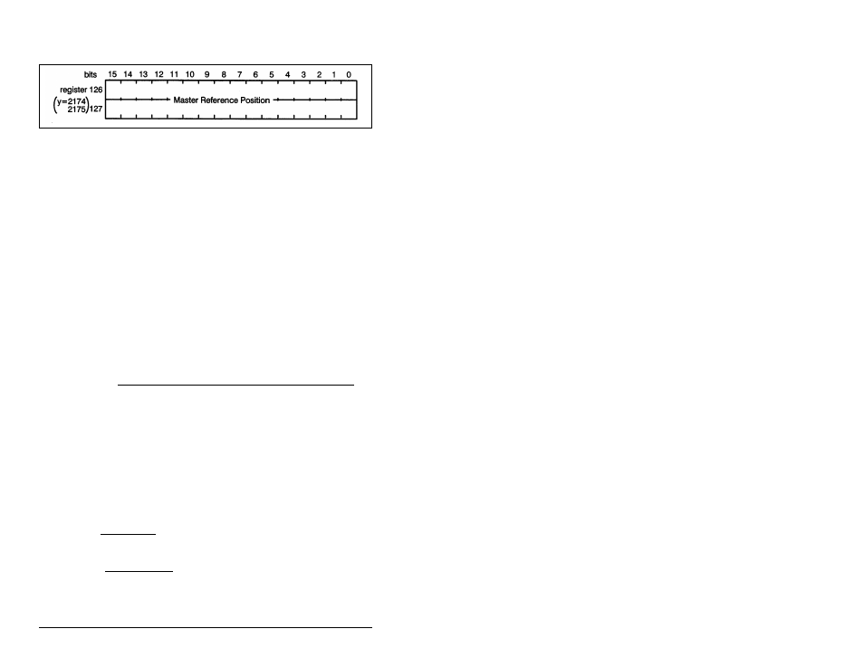
Figure 4.54 – Master Reference Position