Cenelec controlnet ex system diagram, Node 1 – Rockwell Automation 1797-ACNR15 ControlNet Ex Redundant Media Adapter User Manual
Page 20
20 ControlNet Ex Redundant Media Adapter
Publication
1797-5.14 - March 2010
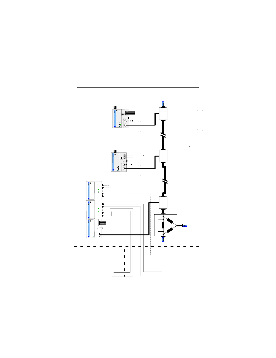
CENELEC ControlNet Ex System Diagram
1
.
.
.
.
.
.
.
.
.
.
.
.
.
.
.
.
CNe
t Ex
trk
trm
3067
0-
M
Con
tr
ol
N
et
Ex
ta
p
Saf
e
A
rea
Ha
za
rd
ou
s Ar
ea
Zone
0
Node
1
Con
tr
ol
N
et
Ex
ta
p
Con
tr
ol
N
et
Ex
ta
p
Cont
ro
lN
et
Ex
ta
p
CNet Ex
tap trm
Ci
<68pF
Li
n
egl
.
ChB
U
o=5.
4V
,
Io
=160mA
,
F
-3
>50
0kH
z
Fl
ex
bu
s
U
o=5
.4V
,
Io
=400mA
,
Po=
2.1
6W
,
C
o=65
μF,
Lo=1
0μ
H
Ch
0
fi
ber
The Co
ax T
ru
nk Cab
le i
s pe
rm
it
te
d t
o have
a mini
mum l
engt
h of
1,
000
m
w
it
h onl
y 2 co
nnect
ed C
ont
ro
lN
et
E
x
Taps
dr
opp
ing
t
o onl
y 250m w
it
h t
he
ma
ximum al
lowed
con
nect
ed Co
nt
ro
lN
et
E
x
Taps of
48.
N
o
de 4 .
.. 48
No
de
3
The
C
ont
ro
lN
et
Ex Syst
em i
s
an
in
tr
in
si
ca
lly
saf
e syst
em
accor
di
ng t
o
EN
500
39.
W
hen i
nst
al
lin
g t
he
syst
em,
t
he
cer
ti
fi
cat
e of
co
nf
or
m
it
y
and t
he
na
ti
on
al i
nst
all
at
ion r
egul
at
ion
s
must
be heed
ed.
Th
e
co
mponen
ts
of
t
he
Co
nt
ro
lN
et
E
x
sys
te
m
and
t
he i
nt
er
connec
ti
ons ar
e shown on t
he ins
ta
lla
ti
on
d
ra
w
ing (
A
-B
Pub
. 1797
-6
.5.
6)
.
For
t
he
tr
ansmi
tt
al bet
ween
t
he saf
e ar
ea and t
he hazar
dou
s
ar
ea
o
nly opt
ic
al
gl
ass-
fi
ber
s
ar
e
pe
rm
it
te
d. The
di
amet
er
o
f a sin
gle
gl
ass-
fi
ber
mus
t be >6u
m
. The power
densi
ty
of
t
he t
ra
nsmit
te
r
di
od
e
mu
st
be <5mW
/mm
2
.
Pr
ot
ect
t
he syst
em aga
in
st
el
ect
ro
st
at
ic
ch
ar
ge.
Post
a si
gn
near
t
he mai
n compon
ent
s of
th
e syst
em:
A
tt
ent
io
n!
A
voi
d el
ect
ro
st
at
ic char
ge
.
179
7-A
C
NR15
/* o
r
RSD-
GW
-E
x2
.CN
179
7-A
C
NR15
/* o
r
RSD-
GW
-E
x2
.CN
Fle
xbus
Uo
=5
.4
V,
Io=400
mA
,
Po
=2.
16W
,
Co=6
5μ
F,
Lo=
10
μH
Power
Sup
ply
Ui
=9
.5
V,
Ii=1A
,
Ci
=<
120nF
,
Li
=n
egl
igi
bl
e
ChA
U
o=5.
4V
,
Io
=160mA
,
F
-3
>50
0kH
z
Power
Sup
ply
Ui
=9
.5
V,
Ii=1A
,
Ci
=<
120nF
,
Li
=n
egl
igi
bl
e
ChB
U
o=5.
4V
,
Io
=160mA
,
F
-3
>50
0kH
z
ChA
U
o=5.
4V
,
Io
=160mA
,
F
-3
>50
0kH
z
75 O
hm
1W
Ci n
egl.
Li negl
.
The ambi
en
t
te
mper
at
ur
e r
ange
of
t
he Cont
ro
lN
et
Ex syst
em i
s -
20 t
o
+7
0
o
C.
N
ear
t
he m
ai
n compo
nent
s of
t
he syst
em a pl
at
e
wi
th
t
he syst
em mar
ki
ng
must
be at
ta
ched.
If
the
system
is
in
stal
le
d i
n
a ca
bi
ne
t the
pl
ate
m
ust be
fi
xed
on
th
e i
nsi
de
of the
ca
bi
ne
t do
or
.
*R
G
6-
C
N
et
is
d
ef
ine
d
as
:
C
abl
e Imped
ance=
75 O
hm + or
-
3 O
hm
C
abl
e Capa
cit
ance
<6nF per
100m
C
abl
e Resi
st
ance>
9.0
8
O
hm per
1
00m
C
abl
e A
tt
enua
ti
on (-
20
to
+70
o
C)
0.
2M
Hz
>
0
.93
dB/10
0m
5MH
z
> 1.3
9dB/1
00m
0.
5M
H
z >
0
.95
dB/10
0m
10MH
z
>1.
86d
B/100
m
1M
H
z >
1.0
7dB/1
00m
20
MH
z >
2.
73dB
/100m
2M
H
z >
1.1
6dB/1
00m
50
MH
z >
4.
33dB
/100m
coax t
ru
nk
cabl
e
coax t
runk cabl
e
Ca
ble
t
ype
118
9A
,
30
92A
, or
3092A
Bl
ue
fr
om manuf
act
ur
er
B
eld
en Wir
e or
t
yp
e
RG
6-
CN
et
*
CNet Ex
trk
tr
m
75 O
hm
1W
Ci
negl
.
Li
ne
gl.
Ci
<
60pF
Li
<
560nH
Li
< 110
0uH
Li
<
1100uH
N
ode 2
17
97
-R
PA
/*
or
RS
D-CF
A-E
x.CN
17
97
-RP
FM/*
or
RS
D
-FC-E
x2
.C
N 3km
17
97
-R
PF
M/
* o
r
RS
D
-FC
-Ex2
.CN 3k
m
Ch
0
fi
ber
Ch
1
fi
ber
Ch
1
fi
be
r
Power
Supp
ly
Ui
=9
.5
V,
Ii=1A
,
Ci
=<
12
0nF
,
Li
=n
eg
lig
ib
le
Uo
=5
.4
V,
Io=
201mA
,
F
-3
>50
0kH
z
Haza
rd
ous Area
Zon
e 0