Description of the controlnet ex system diagrams – Rockwell Automation 1797-ACNR15 ControlNet Ex Redundant Media Adapter User Manual
Page 16
16 ControlNet Ex Redundant Media Adapter
Publication
1797-5.14 - March 2010
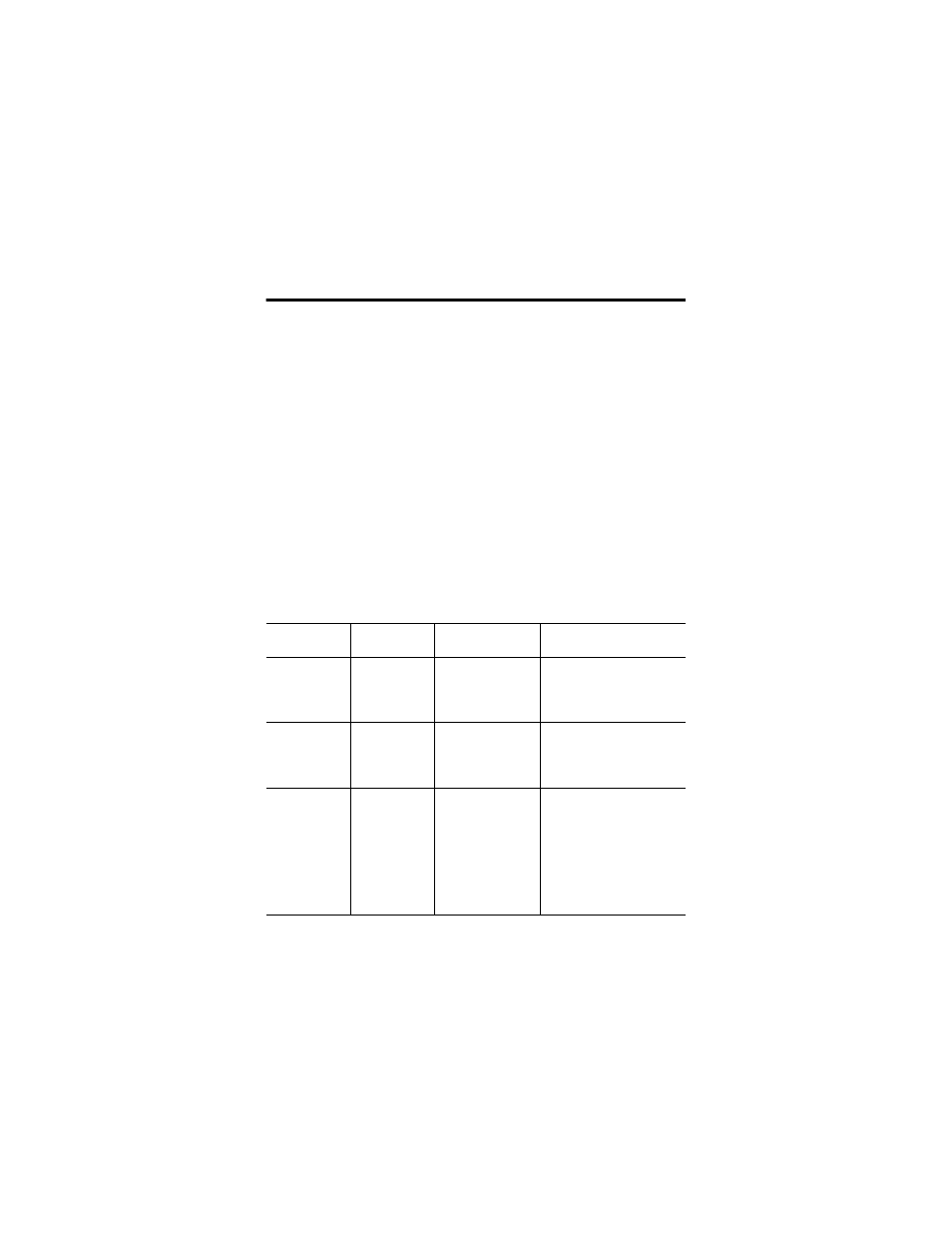
Description of the ControlNet Ex System Diagrams
A maximum of 48 ControlNet Ex nodes may be connected together by 250 m
of coax cable and 48 taps. The distance increases to 1000 m when you use
only 2 taps. See the table below for more information.
The fiber media of the 1797-RPFM can be installed in a hazardous location
(Zone 0, 1 or 2; Class I, Zones 0, 1, and 2; Class I, Division 1 and 2; Class II,
Division 1 and 2; Class III, Division 1 and 2) to connect two 1797-RPFM
modules or they can be installed through different locations into the
nonhazardous location to connect the 1797-RPFM with any approved
associated apparatus.
All cables and fiber media that are not light blue must be marked as IS using
the 1797-EXMK marking kit or other locally approved IS identification or
segregation method.
During the installation of the ControlNet Ex system, all metallic parts must be
isolated to prevent an earth connection (high voltage withstanding of isolating
material must be > 500V ac).
System
Diagram Name
Catalog
Number
Catalog Name
Description
1797-RPA
1797-RPA
ControlNet Ex
Modular Repeater
Adapter
Represents one ControlNet Ex
node and must be connected
to a coax trunk cable by
1797-TPx
1797-RPFM
1797-RPFM
ControlNet Ex Fiber
Repeater Module,
Medium Distance
Allows connection of a
maximum of two devices per
1797-RPA and is powered
directly by 1797-RPA
1797-ACNR15
1797-ACNR15
Redundant Media
ControlNet Ex
Adapter
Represents one ControlNet Ex
node and must be connected
to a coax trunk cable by
1797-TPx - each one with two
redundant output channels
that are connected to different
ControlNet Ex networks (coax
cables and 1797-TPx)