Wiring the modules – Rockwell Automation 1790P-4R0 CompactBlock LDX I/O RTD/Resistance Input Module User Manual
Page 25
Publication 1790-UM002A-EN-P
Installation and Wiring 2-13
To insure that the lead values match as closely as possible:
•
Keep lead resistance as small as possible
.
•
Use quality cable that has a small tolerance impedance rating.
•
Use a heavy-gauge lead wire which has less resistance per foot.
Wire Size and Terminal Screw Torque
Each terminal accepts up to two wires with the following restrictions:
Wiring the Modules
After the module is properly installed, follow the wiring procedure below
and the RTD and potentiometer wiring diagrams on pages 2-15 through
2-16. To ensure proper operation and high immunity to electrical noise,
always use Belden shielded, twisted-pair or equivalent wire.
Table 2.6 Wire Size and Terminal Screw Torque
Wire Type
Wire Size
Terminal Screw
Torque
Retaining Screw
Torque
Solid
Cu-90°C (194°F)
#14 to #22 AWG
0.68 Nm (6 in-lbs)
0.46 Nm (4.1 in-lbs)
Stranded Cu-90°C (194°F)
#16 to #22 AWG
0.68 Nm (6 in-lbs)
0.46 Nm (4.1 in-lbs)
ATTENTION
ÿ
To prevent shock hazard, care should be taken when
wiring the module to analog signal sources. Before
wiring any module, disconnect power from the system
power supply and from any other source to the module.
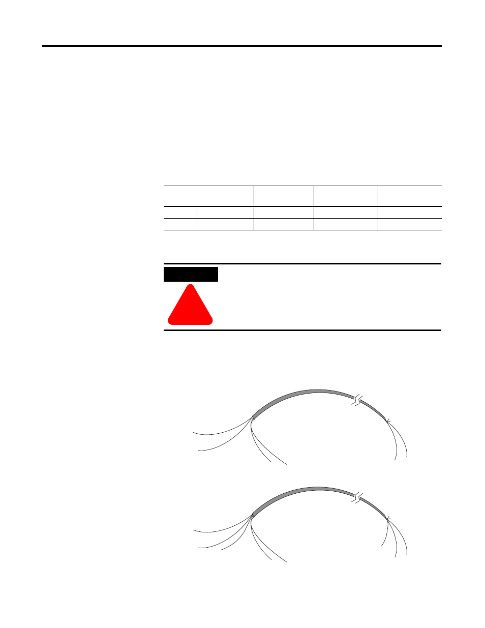
cable
signal wire
signal wire
drain wire
foil shield
signal wire
signal wire
Cut foil shield
and drain wire
cable
signal wire
signal wire
drain wire
foil shield
signal wires (3)
Cut foil shield
and drain wire
signal wire
43250