General diagnostic features, System overview, System operation – Rockwell Automation 1790P-4R0 CompactBlock LDX I/O RTD/Resistance Input Module User Manual
Page 10
Publication 1790-UM002A-EN-P
1-4 Overview
General Diagnostic Features
Module, network, and channel LEDs help you identify the source of
problems that may occur during power-up or during normal channel
operation. The LEDs indicate both status and power. See Chapter 4,
Diagnostics and Troubleshooting, for details on power-up and channel
diagnostics.
System Overview
The modules communicate to the controller or network scanner via the
DeviceNet™ or PROFIBUS network. The modules also receive 24V dc
power through DeviceNet. An external 24V dc auxiliary source is required
to power the RTD/resistance channels.
System Operation
At power-up, the module performs a check of its internal circuits,
memory, and basic functions. If no faults are found during power-up
diagnostics, the module status LED is turned on (green).
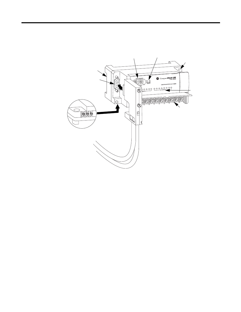
Node Address
Switches
Module and Network
Status Indicators
Panel Mount
Hole
RTD/resistance
Channel Indicators
RTD/resistance Connections
(Terminal block)
PROFIBUS Network
Connector
DIN Rail Slot
Module Power Connector
(underneath module)
PROFIBUS
Connector
31341-M
1790P-T4R0 PROFIBUS DP Module