Rs232 and rs485 interface module – Rockwell Automation 1734-XXXX POINT I/O and ArmorPOINT I/O DeviceLogix User Manual User Manual
Page 108
Publication 1734-UM015A-EN-E - November 2009
106 Peer Data Maps
See the
Very High Speed Counter Input Modules
how to convert Word Data to Double Word in your DeviceLogix program.
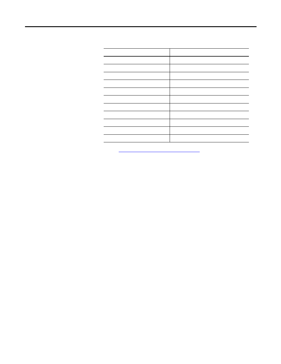
RS232 and RS485 Interface Module
1734-232ASC, 1734-485ASC, 1738-232ASCM12, 1738-485ASCM12
Although the RS232 and RS485 modules can produce up to 132 bytes of data,
only a message of 24 bytes can be consumed by the DeviceLogix module.
The data from these modules can be addressed in the DeviceLogix program
using either bit or word tags.
Peer X (byte 0, bit 0)…Peer X (byte 23, bit 7)
Peer X (word 0)…Peer X (word 11)
Peer X (byte 8, bit 2)
DEC - SSI data count decreasing
Peer X (byte 8, bit 3)
INC - SSI data count increasing
Peer X (byte 8, bit 4)
C1R - Comparator 1 value reached
Peer X (byte 8, bit 5)
C2R - Comparator 2 value reached
Peer X (byte 8, bit 6)
C1ST - Comparator 1 active
Peer X (byte 8, bit 7)
C2ST - Comparator 2 active
Peer X (byte 9, bit 0)
SPF - SSI sensor power fault
Peer X (byte 9, bit 1)
CCF - Coprocessor configuration fault
Peer X (byte 9, bit 2)
CCE - Coprocessor communication error
Peer X (byte 9, bit 3)
IDF - SSI input data fault
Peer X (byte 9, bit 4)
LHON - Latched data is stored
Input Tags for Synchronous Serial Interface Modules (Continued)
Input Tag in DeviceLogix Editor
Data